Supercharge Your Innovation With Domain-Expert AI Agents!

Distribution transformer power flow controller

a technology of power flow controller and distribution transformer, which is applied in the direction of power conversion systems, climate sustainability, ac network circuit arrangements, etc., can solve the problems of inability to effectively regulate the load voltage in real time to compensate, and the conventional distribution transformer also has no capability to compensate for harmonics

Active Publication Date: 2020-06-30
GRIDBRIDGE
View PDF11 Cites 4 Cited by
  • Summary
  • Abstract
  • Description
  • Claims
  • Application Information

AI Technical Summary

Benefits of technology

The patent text describes an apparatus and method for controlling power transfer in a distribution transformer. The apparatus includes an external source terminal, an external load terminal, and a converter circuit. The converter circuit is connected between the external source and load terminals to control power transfer. It can control both real power and reactive power transfer, and may include a transformer and a switching circuit. The converter circuit can also be connected to energy storage devices and a control circuit. The technical effects of this invention include improved control over power transfer in a distribution transformer, reduced voltage drop, and increased efficiency.

Problems solved by technology

Although conventional distribution transformers are rugged and relatively efficient devices, they generally have limited control capabilities.
For example, the impedance of the load connected to a distribution transformer typically dictates reactive power flow through the transformer, as typical conventional distribution transformers have no ability to control reactive power flow.
In addition, while some traditional distribution transformers may be able to adjust voltage provided to the load using mechanisms such as tap changers, such capabilities are typically not used in a distribution transformer and, even if used, typically cannot effectively regulate the load voltage in real time to compensate for transient sags and spikes.
Conventional distribution transformers also typically have no capability to compensate for harmonics introduced by non-linear loads.

Method used


Image

  • Distribution transformer power flow controller
  • Distribution transformer power flow controller
  • Distribution transformer power flow controller

Examples


Embodiment Construction

[0030]Specific exemplary embodiments of the inventive subject matter now will be described with reference to the accompanying drawings. This inventive subject matter may, however, be embodied in many different forms and should not be construed as limited to the embodiments set forth herein; rather, these embodiments are provided so that this disclosure will be thorough and complete, and will fully convey the scope of the inventive subject matter to those skilled in the art. In the drawings, like numbers refer to like elements. It will be understood that when an element is referred to as being “connected” or “coupled” to another element, it can be directly connected or coupled to the other element or intervening elements may be present. As used herein the term “and / or” includes any and all combinations of one or more of the associated listed items.

[0031]The terminology used herein is for the purpose of describing particular embodiments only and is not intended to be limiting of the i...


PUM


Abstract

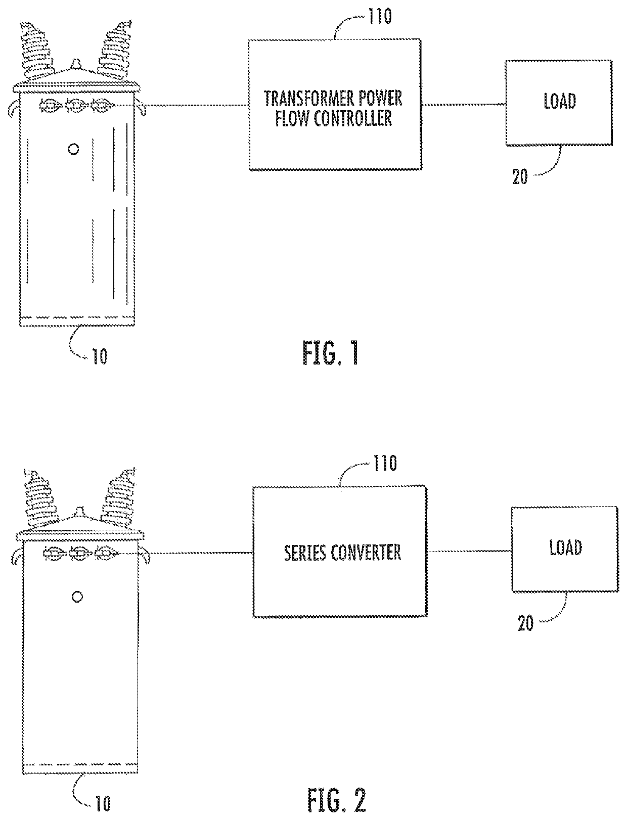
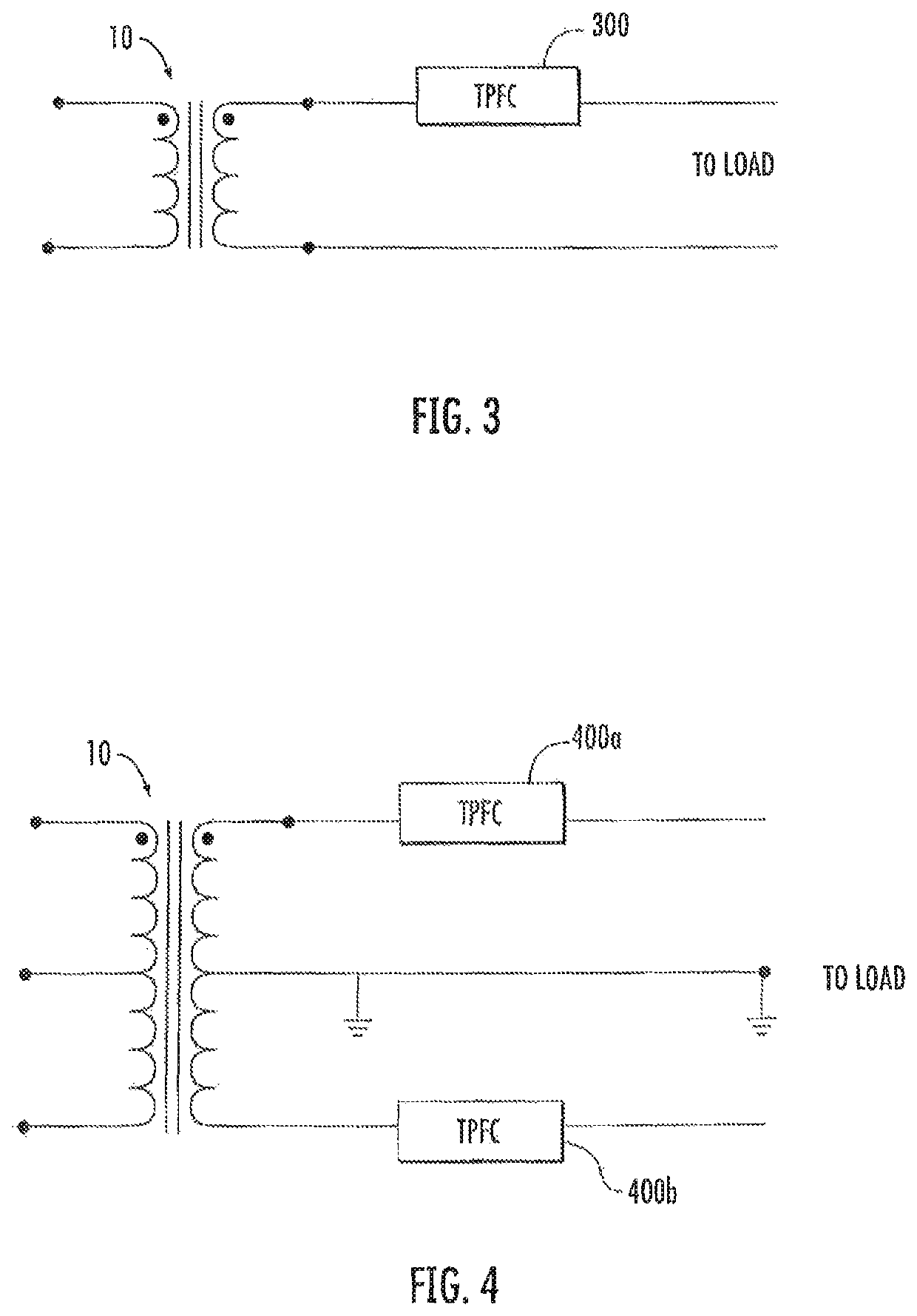
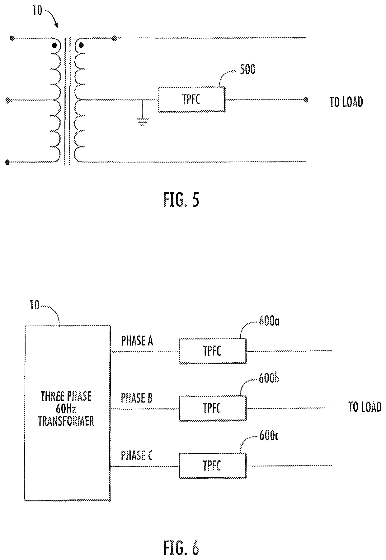
A distribution transformer power flow controller apparatus includes at least one external source terminal configured to be coupled to a distribution transformer, at least one external load terminal configured to be coupled to a load, and a converter circuit configured to be coupled between the at least one external source terminal and the at least one external load terminal to provide series connection of the converter circuit with the load and to control a power transfer of the distribution transformer. The converter circuit may be configured to control a reactive power transfer of the distribution transformer. The converter circuit may also be configured to control a reactive power transfer and a real power transfer. In some embodiments, the converter circuit may be configured to be coupled to at least one energy storage capacitor, at least one battery and / or at least one power generation device.

Description

CROSS-REFERENCE TO RELATED APPLICATION[0001]The present application is a continuation-in-part of U.S. application Ser. No. 13 / 724,846 titled “Distribution Transformer Power Flow Controller” filed on Dec. 21, 2012, which is incorporated herein by reference in its entirety.STATEMENT REGARDING FEDERALLY SPONSORED RESEARCH OR DEVELOPMENT[0002]Not applicable to this application.BACKGROUNDField of the Disclosure[0003]The inventive subject matter relates to power distribution apparatus and methods and, more particularly, to distribution transformer apparatus and methods.Background of the Disclosure[0004]Electric utility systems typically distribute power using transmission and distribution networks. High voltage (e.g., 100 kV and above) transmission networks are used to convey power from generating stations to substations that feed lower voltage (e.g., less than 100 kV) distribution networks that are used to carry power to homes and businesses. In a typical distribution network used in res...

Claims


Application Information

Patent Timeline
Patent Type & Authority Patents(United States)
IPC IPC(8): H02M1/42
CPCH02M1/4208H02J3/1814H02M1/42Y02B70/10Y02E40/10
Inventor ECKHARDT, CHADWATTS, STEPHEN TIMOTHY
Owner GRIDBRIDGE
Features
  • R&D
  • Intellectual Property
  • Life Sciences
  • Materials
  • Tech Scout
  • Unparalleled Data Quality
  • Higher Quality Content
  • 60% Fewer Hallucinations
Learn More