Crossover for multi-driver loudspeakers

Active Publication Date: 2020-06-30
MODAFFERI RICHARD
View PDF13 Cites 8 Cited by
  • Summary
  • Abstract
  • Description
  • Claims
  • Application Information

AI Technical Summary

Benefits of technology

[0013]In accordance with the present invention there are provided improved circuit topologies that eliminate the slight amplitude and phase errors at or near the individual crossover frequencies in the crossover network. First, an additional “pole” is added in the transfer function(s) of

Problems solved by technology

He deduced that a localized phase error might possibly be respon

Method used


Image

  • Crossover for multi-driver loudspeakers
  • Crossover for multi-driver loudspeakers
  • Crossover for multi-driver loudspeakers

Examples


Example

[0027]The present invention provides improved crossover networks for two-way, three-way and multi-way loudspeaker systems wherein coloration anomalies at or near one or more the crossover frequencies are greatly decreased or eliminated.

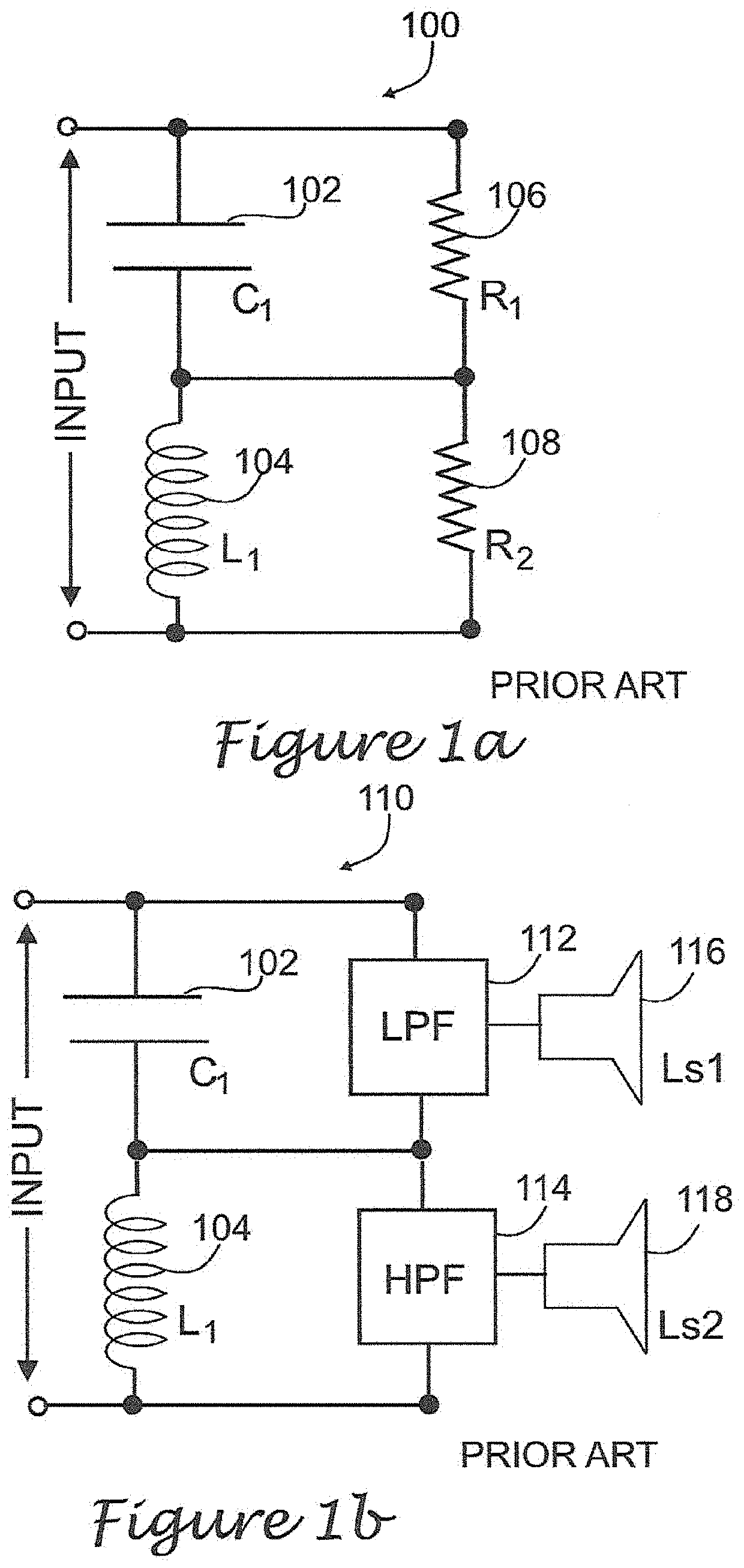
[0028]High fidelity loudspeaker systems are typically realized by dividing the audio frequency spectrum into two or more discrete frequency bands that are then applied to appropriate loudspeaker drivers. To divide the audio frequency spectrum, two or more individual crossover filters are used. By matching the frequency response characteristic of each loudspeaker driver with the output of each crossover filter, a complete loudspeaker system may be assembled.

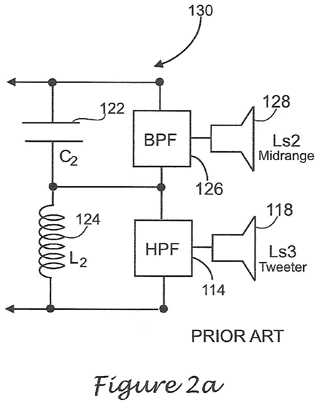
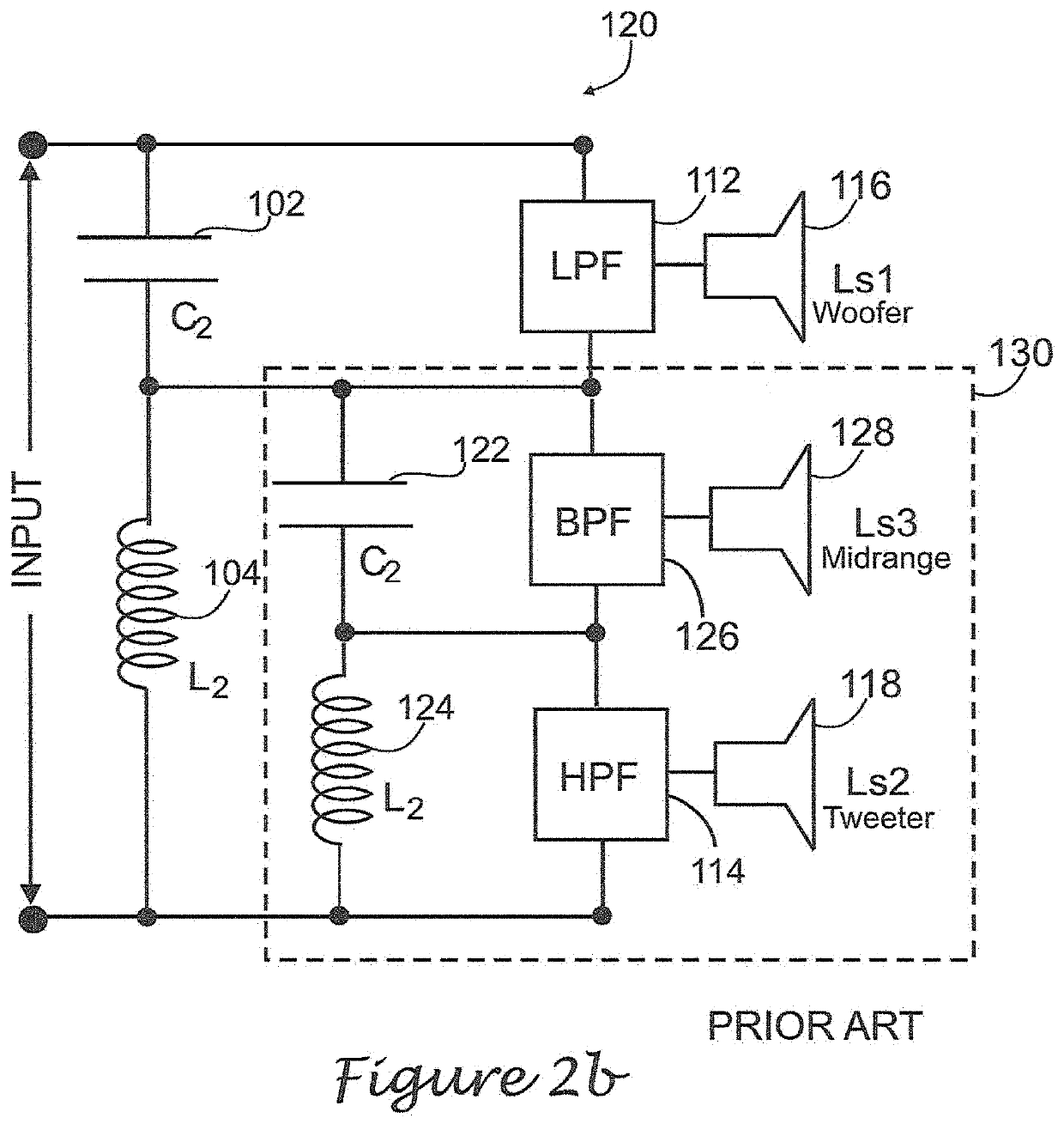
[0029]Crossover filters belong to three general types: (1) low-pass filters for woofers (bass frequencies); (2) band-pass filters for midrange drivers (middle frequencies in the range of the human voice), and (3) high-pass filters for tweeter drivers (high frequencies up to 20 kHz). Woofer, midrange...


PUM


Abstract

Crossover networks modified to render audible colorations or frequency/phase emphases observed in some crossover networks of the prior art. Circuit topologies of prior art crossover networks are modified such that an additional pole appears in the transfer functions of one or more low-frequency pass crossover filters. In addition, the characteristic input impedance of one branch of the modified crossover network is reduced, typically to a value of approximately one-half the design characteristic impedance of the unmodified crossover networks.

Description

RELATED APPLICATIONS[0001]This application is related to U.S. Pat. No. 4,403,112 for “Phase-Shift Low Frequency Loudspeaker System” issued Sep. 6 1983, hereinafter the '112 patent; and U.S. Pat. No. 7,085,389 BI for “Infinite Slope Loudspeaker Crossover Filter” issued Aug. 2, 2006, hereinafter the '389 patent, all issued to Richard Modafferi and included herein in their entirety by reference.FIELD OF THE INVENTION[0002]The present invention pertains to loudspeaker systems and, more particularly, to crossover networks displaying a combination of both steep and shallow slopes in filter amplitude responses and presenting substantially constant input impedances at their inputs. The present invention also provides improved crossover filter phase / delay responses relative to crossover filters of the prior art.BACKGROUND OF THE INVENTION[0003]High-Fidelity loudspeaker systems are generally realized by dividing the audible frequency spectrum into two or more frequency bands and then applying...

Claims


Application Information

Patent Timeline
IPC IPC(8): H04R3/04H04R3/12H04R3/14H04R1/22
CPCH04R3/14H04R1/227H04R3/04H04R1/26
Inventor MODAFFERI, RICHARD
Owner MODAFFERI RICHARD
Why Eureka
Try Eureka