Amplifier apparatus for use with a sensor

Active Publication Date: 2005-09-08
TEXAS INSTR INC
View PDF27 Cites 0 Cited by
  • Summary
  • Abstract
  • Description
  • Claims
  • Application Information

AI Technical Summary

Benefits of technology

[0008] It is, therefore, an object of the present invention to provide a signal amplifier apparatus that accommodates economic design for low band pass corner frequency.

Problems solved by technology

The presence of such a DC bias may cause problems if the DC signal is passed on to amplifying elements.
This new technology has occasioned new design challenges.
One such challenge has been that when using perpendicular magnetic recording, low corner frequency fLF is preferably about one-tenth the value of low corner frequency fLF values required for longitudinal recording applications where the magnetic recording medium is magnetized substantially in the film plane of the medium.
Prior art signal amplifiers, especially signal amplifiers for use with a read head in an information storage device, have heretofore been difficult to produce economically with low band pass corner frequency fLF.

Method used


Image

  • Amplifier apparatus for use with a sensor
  • Amplifier apparatus for use with a sensor
  • Amplifier apparatus for use with a sensor

Examples


Embodiment Construction

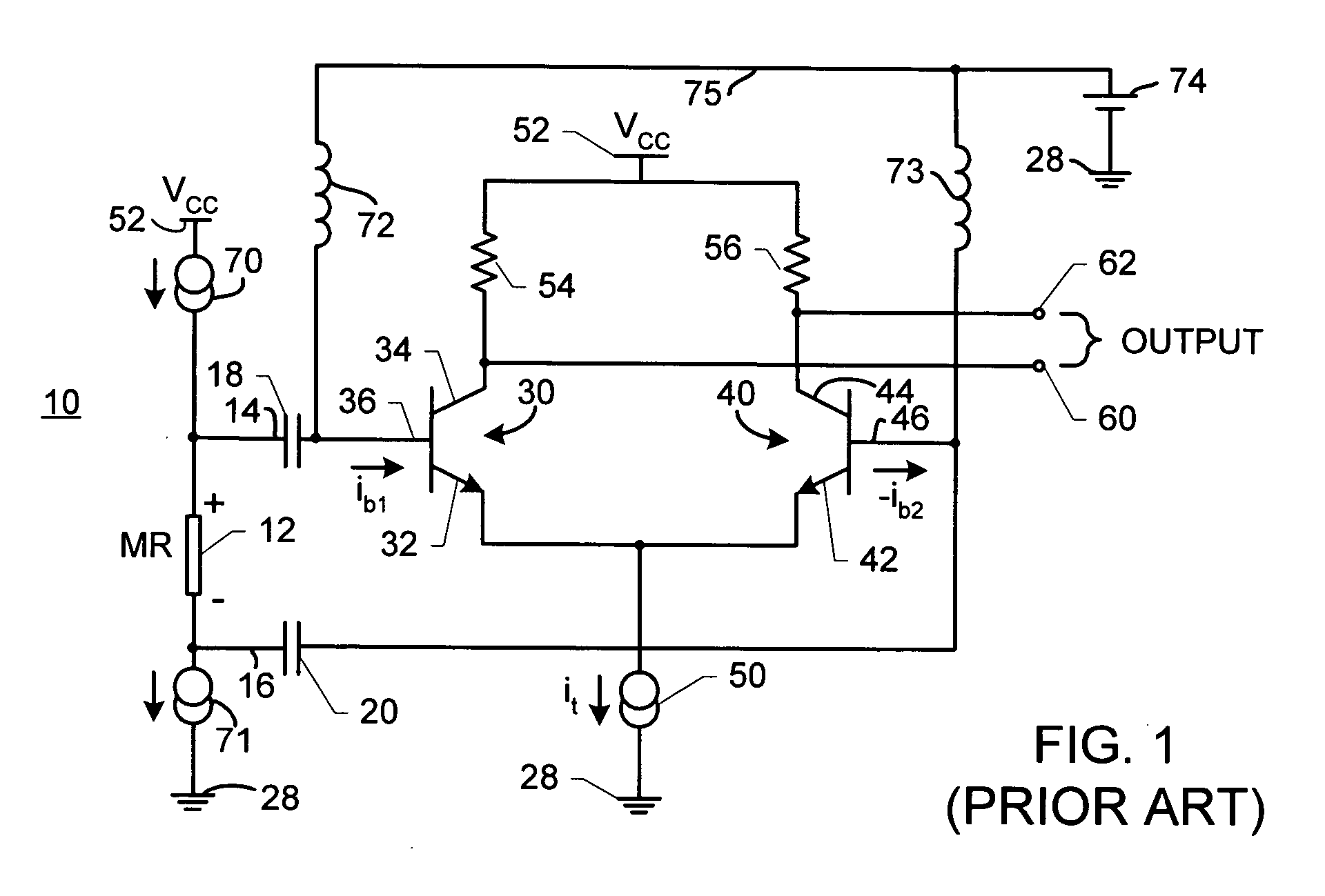
[0013]FIG. 1 is an electrical schematic illustration of a first example of a prior art differential amplifier for use with a read head. In FIG. 1, a read amplifier circuit 10 (sometimes also referred to as a read front-end) is attached to a magneto-resistive element 12 via connection leads 14, 16 connected in parallel. Magneto-resistive element 12 is coupled with a supply voltage VCC at a supply voltage locus 52 via a current source 70. Magneto-resistive element 12 is also coupled with ground 28 (or another potential appropriate to establish the required DC bias for magneto-resistive element 12) via a current source 71. Current sources 70, 71 apply DC (direct current) bias so that flux from a medium being read (not shown in FIG. 1) by magneto-resistive element 12 may be converted to a voltage change or a current change for use by read amplifier circuit 10. A capacitor 18 is coupled with connection lead 14. A capacitor 20 is coupled with connection lead 16. Capacitors 18, 20 block lo...


PUM


Abstract

An amplifier apparatus for use with a sensor includes: (a) a first and a second amplifying circuit segment coupled with the sensor and cooperating to effect substantially balanced handling of signals received from the sensor; the first amplifying circuit segment includes a first transistor device; the second amplifying circuit segment includes a second transistor device; (b) a countercurrent unit coupled with the first and second amplifying circuit segments for receiving a first indicator signal from the first transistor device and a second indicator signal from the second transistor device; the first indicator signal represents a first parameter in the first transistor device; the second indicator signal represents a second parameter in the second transistor device; the countercurrent unit provides feedback signals to at least one of the first transistor and second transistor devices to reduce input impedance of the apparatus.

Description

[0001] This application claims benefit of prior filed copending Provisional Patent Application Ser. No. 60 / 549,375, filed Mar. 2, 2004.BACKGROUND OF THE INVENTION [0002] The present invention is directed to signal amplifiers used with a sensor such as a read head in an information storage device, and especially to such signal amplifiers having reduced input impedance. [0003] There are many important goals in designing and operating an amplifier for use with a sensor. One such goal is low band pass corner frequency. Sensors such as magneto-resistive sensing elements require a direct current (DC) bias applied across them to operate correctly. The presence of such a DC bias may cause problems if the DC signal is passed on to amplifying elements. A low band pass corner frequency permits sensing of lower frequency signals while still rejecting DC signals and therefore contributes to a truer sensing of signals indicated by the sensor. [0004] Needs for greater magnetic storage density in i...

Claims


Application Information

Patent Timeline
IPC IPC(8): G11B5/02G11B5/09
CPCG11B5/02H03F2203/45318H03F3/45085G11B2005/0018
Inventor HASHIZUME, MOTOMU
Owner TEXAS INSTR INC
Why Eureka
Try Eureka