
Clutch, drive transmission device and image forming apparatus

a transmission device and drive technology, applied in mechanical actuated clutches, electrographic processes, instruments, etc., can solve the problems of increasing the number of components of the reverse input cutoff clutch, increasing the cost, and affecting the operation of the clutch, so as to achieve a simple and inexpensive constitution

Active Publication Date: 2020-07-07
CANON KK
View PDF38 Cites 3 Cited by
  • Summary
  • Abstract
  • Description
  • Claims
  • Application Information

AI Technical Summary

Benefits of technology

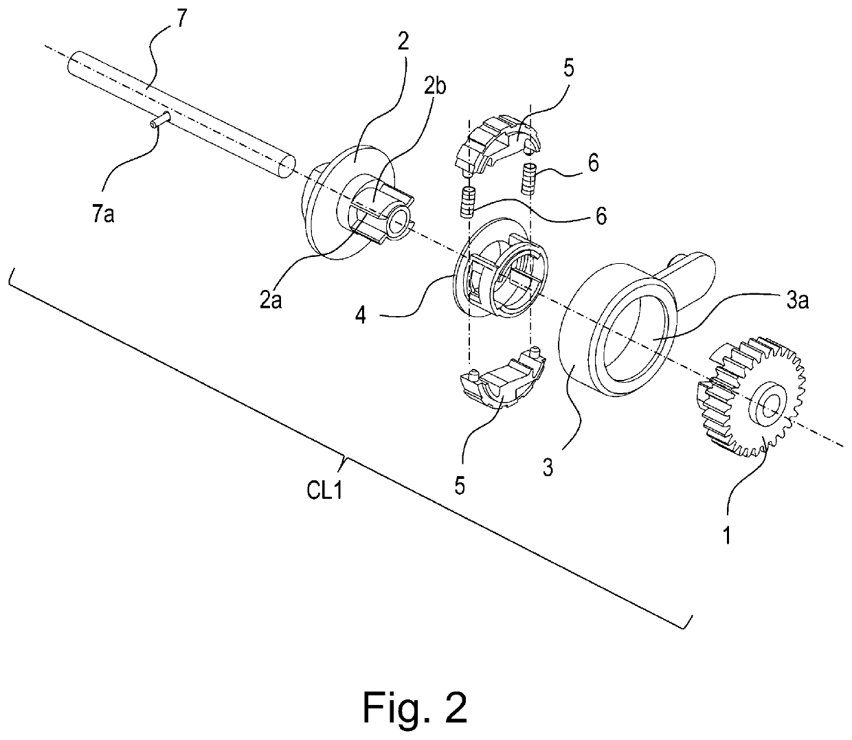
The present invention provides a clutch with a simple and inexpensive constitution. The clutch includes an input member, an outputting member, a stationary member, and a contact member. The outputting member rotates in contact with the inputting member when the input torque is inputted, and it is spaced from the inputting member when a reverse input torque is inputted. The contact member has an arcuate first contact surface and a second contact surface, and it prevents the outputting member from rotating when a reverse input torque is inputted by urging the first contact surface against the stationary member.

Problems solved by technology

From the above-described reasons, the conventional reverse input cutoff clutches caused a problem such that a structure was liable to be complicated since the structure included the intermediary members at the several positions.
Further, the problem also led to an increase in number of component parts constituting the reverse input cutoff clutch and an increase in cost due to use of an expensive material such as the metallic material.

Method used


Image

  • Clutch, drive transmission device and image forming apparatus
  • Clutch, drive transmission device and image forming apparatus
  • Clutch, drive transmission device and image forming apparatus

Examples


first embodiment

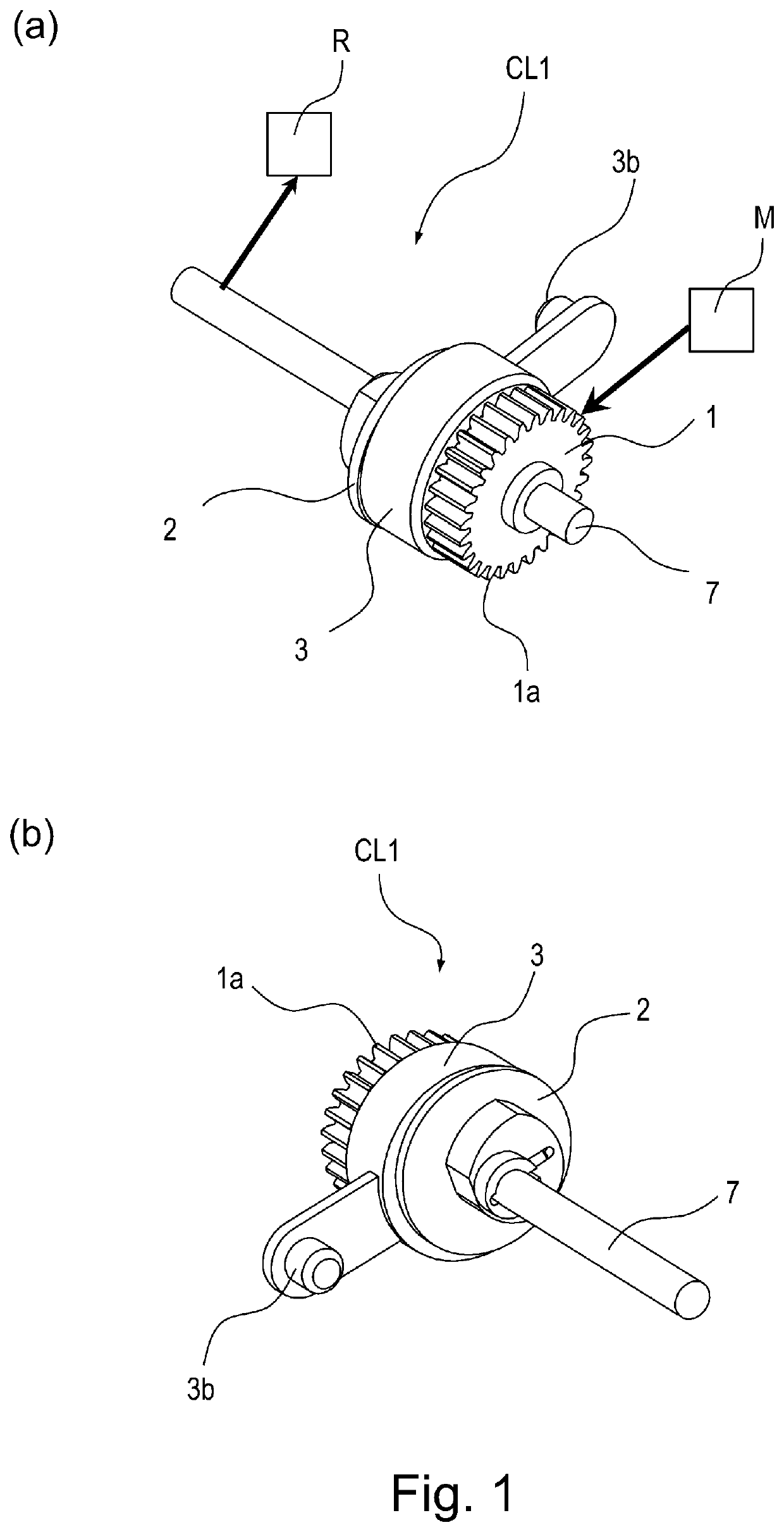
[0056]The reverse input cutoff clutch in the present invention not only transmits an input torque from an inputting member to an outputting member but also cuts off a reverse input torque inputted from the outputting member toward the inputting member when the reverse input torque generates, for example. This reverse input cutoff clutch is incorporated in a drive transmission device for suppressing that the outputting member rotates at a driving speed faster than a driving speed of the inputting member.

[0057]In this embodiment, in an electrophotographic image forming apparatus, the reverse input cutoff clutch is incorporated in the drive transmission device for transmitting a driving force to a cam member for spacing rollers of a fixing roller pair press-contacted by a spring or the like. Incidentally, the apparatus in which the reverse input cutoff clutch in this embodiment is incorporated is not limited to the image forming apparatus.

[0058]A constitution of the reverse input cutof...

second embodiment

[0098]A constitution of a reverse input cutoff clutch in Second Embodiment of the present invention will be described with reference to FIGS. 11 to 16. FIG. 11 is a perspective view of a reverse input cutoff clutch CL2 (hereinafter simply referred to as a clutch CL2) before assembling. Incidentally, constituent elements similar to those in First Embodiment described above are represented by adding similar reference numerals or symbols and will be omitted from description.

[Structure of Clutch CL2]

[0099]As shown in FIG. 11, the clutch CL2 includes an inputting member 1 to which an input torque of a driving source M1 is inputted, an outputting member 2 to which the input torque is transmitted, a stationary member 3 of which rotation is constrained, a pair of contact members 5 and two urging members 6 for urging the contact member 5. The respective members constituting the clutch CL2 are disposed coaxially with a rotation shaft 7, and the members other than the stationary member 3 are p...

third embodiment

[0117]A constitution of a reverse input cutoff clutch in Third Embodiment of the present invention will be described with reference to FIGS. 17 to 21. FIG. 17 is a perspective view of a reverse input cutoff clutch CL3 (hereinafter simply referred to as a clutch CL3) before assembling. Incidentally, constituent elements similar to those in First and Second Embodiments described above are represented by adding similar reference numerals or symbols and will be omitted from description.

[Structure of Clutch CL3]

[0118]As shown in FIG. 17, the clutch CL3 includes an inputting member 1 to which an input torque of a driving source M1 is inputted, an outputting member 20 to which the input torque is transmitted, a stationary member 3 of which rotation is constrained. The clutch CL3 further includes a contact member 5 provided with rotation contact portions 5g and two urging members 6 for urging the contact member 5. The above-described members constituting the clutch CL3 are disposed coaxiall...


PUM


Abstract

A clutch includes a rotatable inputting member, a rotatable outputting member, a stationary member, and a contact member. The outputting member includes an output contact portion. The contact member is positioned between the outputting member and the stationary member and includes an arcuate first contact surface and a second contact surface. When the input torque for rotating the inputting member is inputted, the outputting member and the contact member rotate in contact with the inputting member. When a reverse input torque for rotating the outputting member is inputted, the outputting member is spaced from the inputting member, and the output contact portion of the outputting member urges the first contact surface against the stationary member by urging the second contact surface of the contact member thereby to prevent rotation of the outputting member.

Description

FIELD OF THE INVENTION AND RELATED ART[0001]The present invention relates to a clutch having a function of not only transmitting an input torque from an inputting member to an outputting member but also blocking (cutting off) a torque inputted from the outputting member toward the inputting member, and relates to a drive transmission device including the clutch and an image forming apparatus including the drive transmission device.[0002]Conventionally, as a drive transmitting means for not only transmitting an input torque from an inputting member side to an outputting member side but also blocking a torque inputted from the outputting member side toward the inputting member side (this torque is referred to as a reverse input torque), there are reverse input cutoff clutches (Japanese Laid-Open Patent Application (JP-A) 2008-101715 and JP-A 2009-198949. JP-A 2008-101715 discloses an example of the reverse input cutoff clutch.[0003]The reverse input cutoff clutch disclosed in JP-A 200...

Claims


Application Information

Patent Timeline
Patent Type & Authority Patents(United States)
IPC IPC(8): F16D13/16F16D23/12G03G15/00B65H1/14F16D41/06
CPCF16D23/12F16D13/16F16D41/06G03G15/757F16D2023/123F16D2041/0606F16D2041/0601F16D41/064G03G15/20F16D3/02F16D67/02F16D51/22F16D51/50
Inventor CHINO, HIDETO
Owner CANON KK
Learn More