Power conversion systems and associated methods

a power conversion system and power conversion technology, applied in the direction of dynamo-electric converter control, electric generator control, dc-ac conversion without reversal, etc., can solve the problems of increased control complexity associated with the firing of multiple switches, increased cost and electrical losses,

Active Publication Date: 2020-07-14
GENERAL ELECTRIC CO
View PDF23 Cites 0 Cited by
  • Summary
  • Abstract
  • Description
  • Claims
  • Application Information

AI Technical Summary

Problems solved by technology

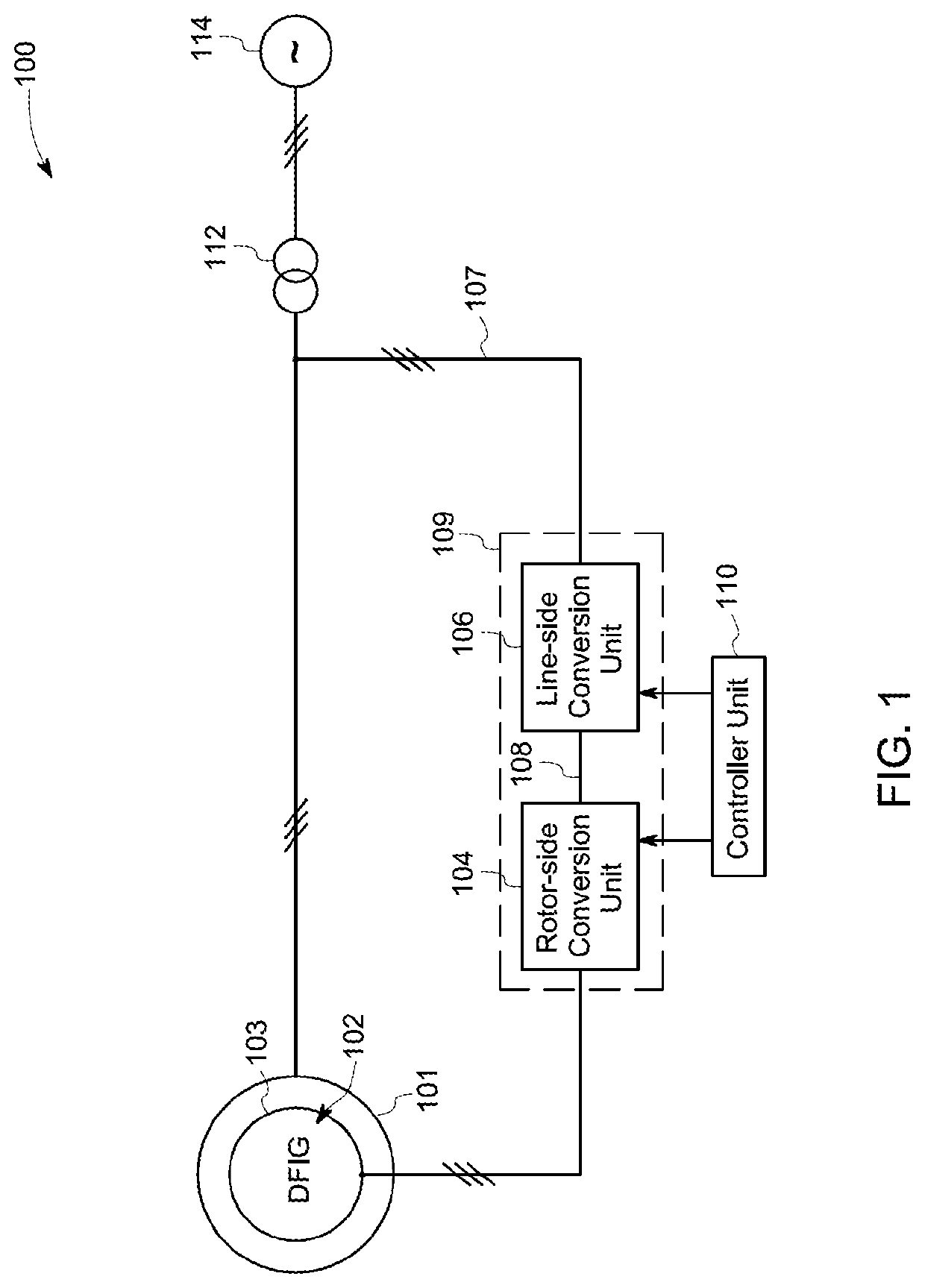
The power generation system further employs bulky three-winding transformers to provide power to the grid from the back-to-back converter.
Use of the multiple switches in the power conversion unit results in increased cost and electrical losses.
Further, use of the multiple switches is associated with increased control complexity associated with firing of these multiple switches.
In addition, failure of a converter of the combination of converters in the line-side converter or failure of a switch of the multiple switches employed in the line-side converter may adversely affect a value of a line-side output.
Further, as will be appreciated, in instances of such failures, reliability of the power conversion unit employing such line-side converter is compromised.

Method used


Image

  • Power conversion systems and associated methods
  • Power conversion systems and associated methods
  • Power conversion systems and associated methods

Examples


Embodiment Construction

[0014]Unless defined otherwise, technical and scientific terms used herein have the same meaning as is commonly understood by one of ordinary skill in the art to which this disclosure belongs. The terms “first”, “second”, and the like, as used herein do not denote any order, quantity, or importance, but rather are used to distinguish one element from another. Also, the terms “a” and “an” do not denote a limitation of quantity, but rather denote the presence of at least one of the referenced items. The term “or” is meant to be inclusive and mean one, some, or all of the listed items. The use of “including,”“comprising” or “having” and variations thereof herein are meant to encompass the items listed thereafter and equivalents thereof as well as additional items. The terms “connected” and “coupled” are not restricted to physical or mechanical connections or couplings, and can include electrical connections or couplings, whether direct or indirect. Furthermore, the terms “circuit” and ...


PUM


Abstract

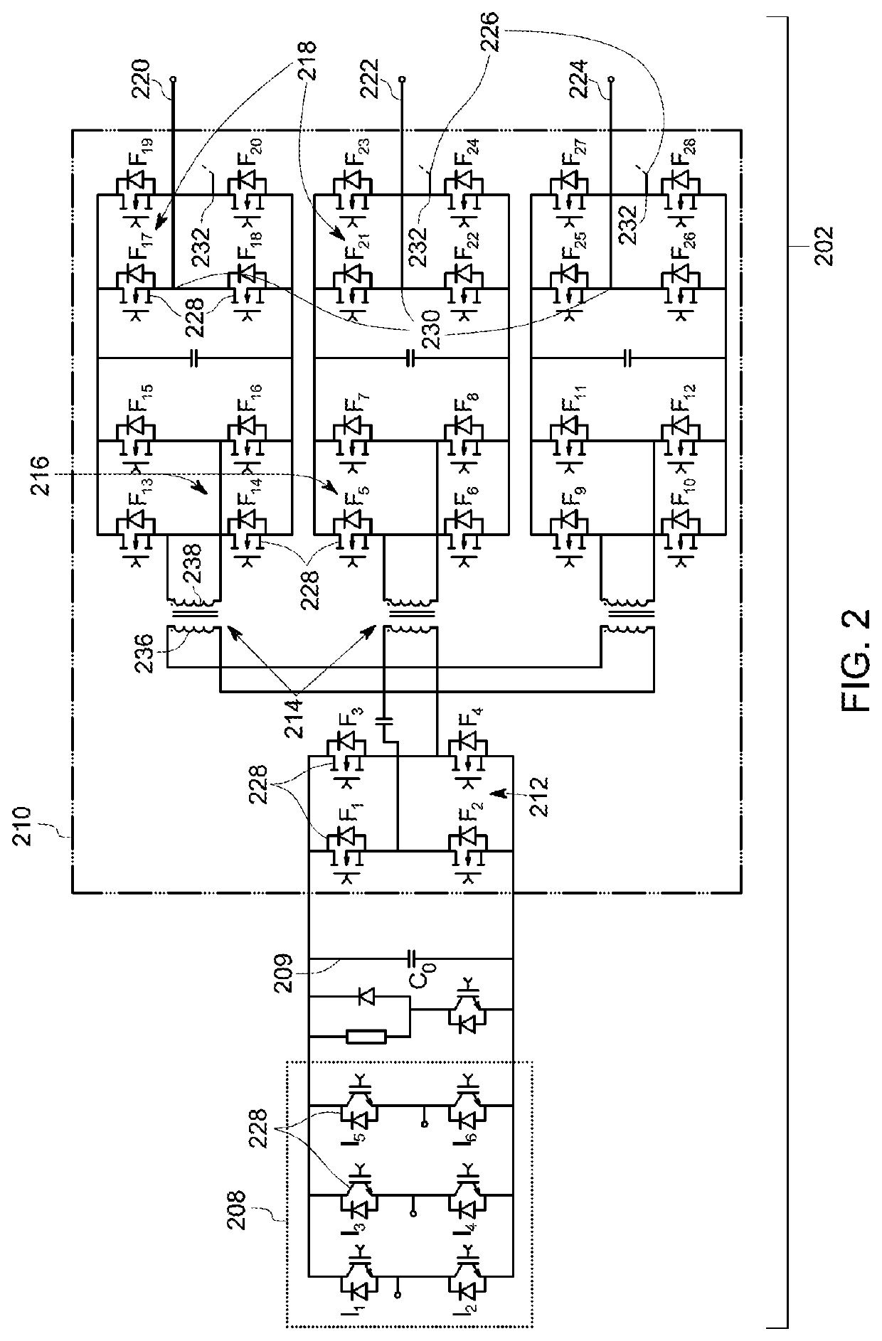
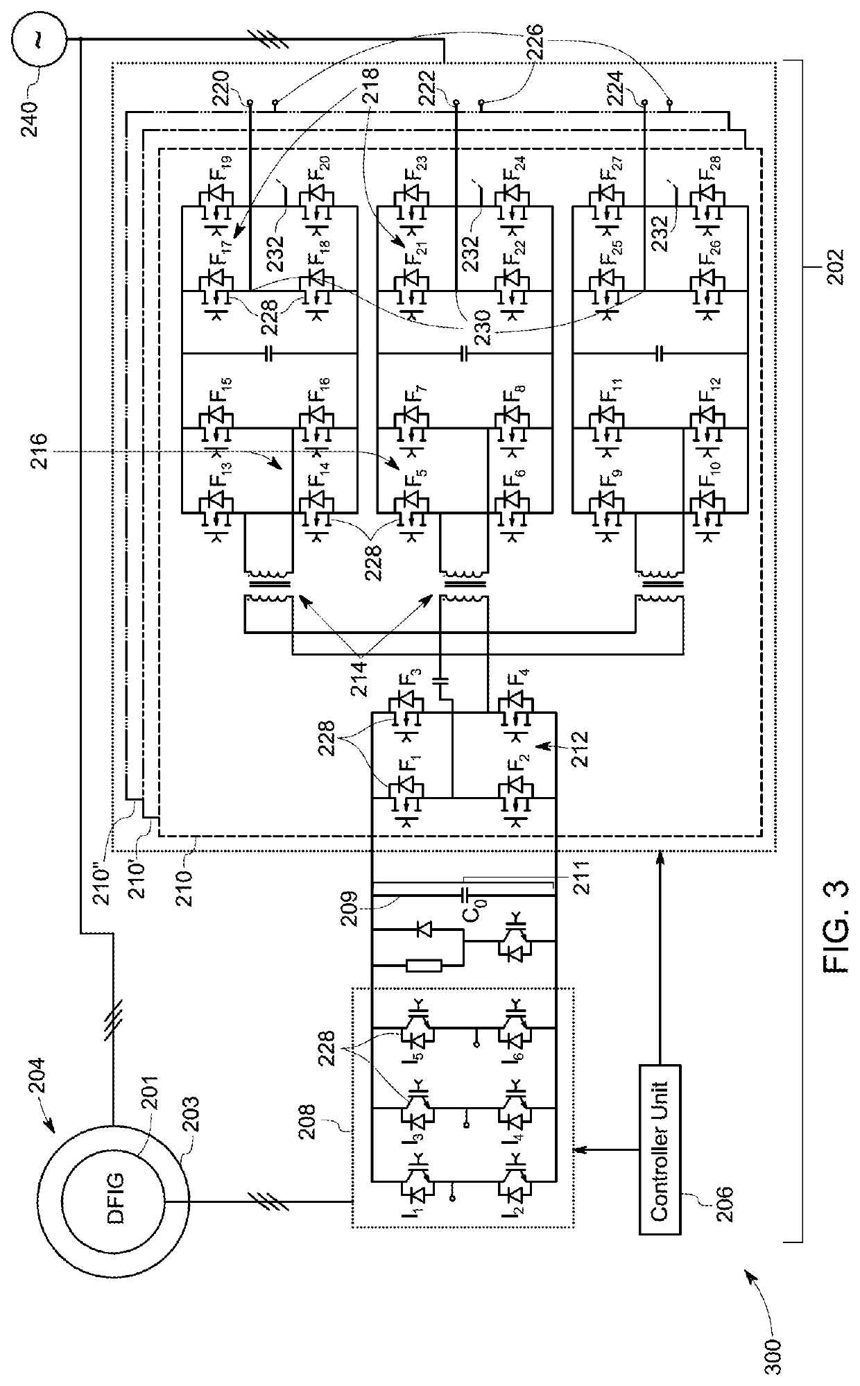
A wind power generation system including a doubly fed induction generator (DFIG) of a wind turbine is presented. The DFIG includes a rotor and a stator, a rotor-side conversion unit coupled to the rotor, a direct current (DC) link, and at least one line-side conversion unit coupled to the rotor-side conversion unit via the DC link and coupled to the stator of the DFIG. The at least one line-side conversion unit includes exactly one first converter, high frequency transformers, and second converters, where each of the second converters is coupled to the first converter via a respective high frequency transformer, and inverters, where each of the inverters is coupled to a respective second converter and includes an alternative current (AC) phase terminal.

Description

BACKGROUND OF THE INVENTION[0001]One or more embodiments of the present specification relate to power generation systems and more particularly to power conversion unit employed in the power generation systems.[0002]Typically, a power generation system includes a power conversion unit such as a back-to-back converter. The back-to-back converter includes a rotor-side converter and a line-side converter coupled to the rotor-side converter via a direct current (DC) link. A primary function of the back-to-back converter is to regulate active power and reactive power fed into a grid. The power generation system further employs bulky three-winding transformers to provide power to the grid from the back-to-back converter.[0003]Usually, a combination of converters is used as a line-side converter to enhance a value of an output generated by the line-side converter. Further, the rotor-side and line-side converters of the power generation systems include multiple switches. Use of the multiple ...

Claims


Application Information

Patent Timeline
Patent Type & Authority Patents(United States)
IPC IPC(8): H02P9/00H02K7/18H02M7/48H02M5/458H02M7/49H02M5/22
CPCH02K7/183H02M7/4807H02M5/4585H02P9/007Y02B70/145H02M2007/4815Y02E10/76H02M7/49Y02B70/1441H02P2201/00H02M5/225Y02B70/10H02M7/4815
Inventor JHA, KAPILTIWARI, ARVIND KUMARSHUKLA, SAURABHRAY, OLIVE
Owner GENERAL ELECTRIC CO
Why Eureka
Try Eureka