Method and apparatus for continuously controlling the dynamic range from an analog-to-digital converter

Active Publication Date: 2006-01-31
WSOU INVESTMENTS LLC
View PDF8 Cites 121 Cited by
  • Summary
  • Abstract
  • Description
  • Claims
  • Application Information

AI Technical Summary

Benefits of technology

[0008]The required number of bits is another way of saying or indicating the dynamic range of the ADC when used in dynamic receiving conditions. As such, the ADC with such dynamic range capability is able to be used with the minimum number of bits or minimum dynamic range necessary for receiving the radio frequency channel under dynamic radio frequency conditions and therefore optimizes the power consumption associated with the ADC and hence, the radio receiver. By determining the required number of bits of the ADC in use under dynamic conditions, the power consumption can be optimized by scaling the biasing current, reducing the supply voltage, removing the number of stages from the converter and/or any other possible means to reduce overall power consumption.
[0009]The method of continuously controlling the dynamic range of an ADC according to the present invention is performed by measuring the received radio frequency channel and other signals which may be present at the antenna so as to determine the existing reception conditions based on the signal level of the desired radio channel and any other interfering signals, including other interfering radio frequency channels. The method used is an algorithm to determine the appropriate number of bits (dynamic range) required in the ADC to allow decoding of the desired radio channel. Optionally, the algorithm can also scale the amplification of preceding stages prior to the analog-to-digital conversion and select the correct number of bits for the conversion by the ADC. The overall result leads to a more optimized power consumption of the radio receiver.
[0010]The present invention provides for continuously controlling the dynamic range of an ADC by providing to the ADC a control word whi

Problems solved by technology

The overall result leads to a more optimiz

Method used


Image

  • Method and apparatus for continuously controlling the dynamic range from an analog-to-digital converter
  • Method and apparatus for continuously controlling the dynamic range from an analog-to-digital converter
  • Method and apparatus for continuously controlling the dynamic range from an analog-to-digital converter

Examples


Embodiment Construction

Introduction

Radio Receiver 20

[0024]The acronyms used throughout the figures and the associated discussions are presented in Table 1.

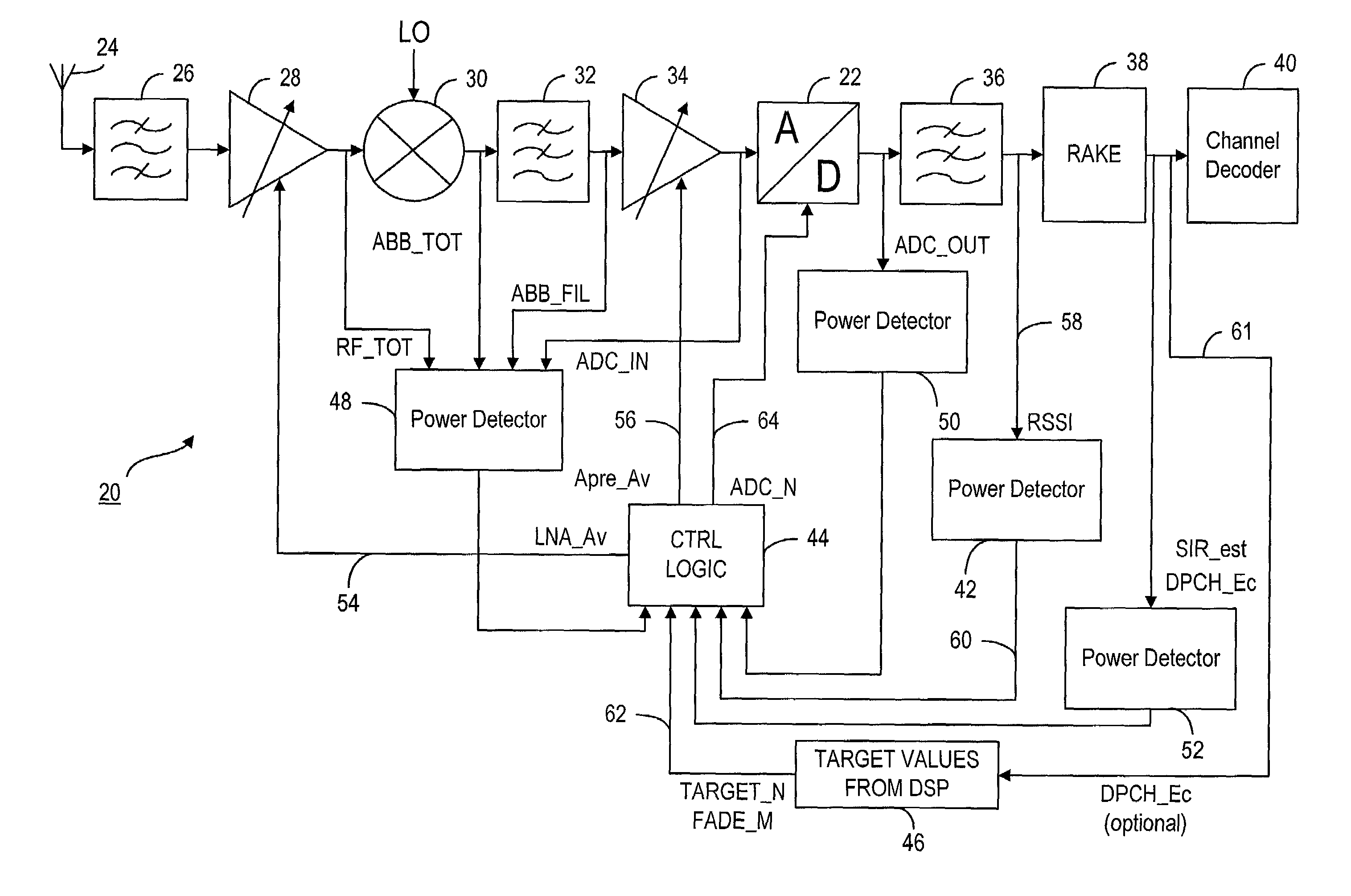
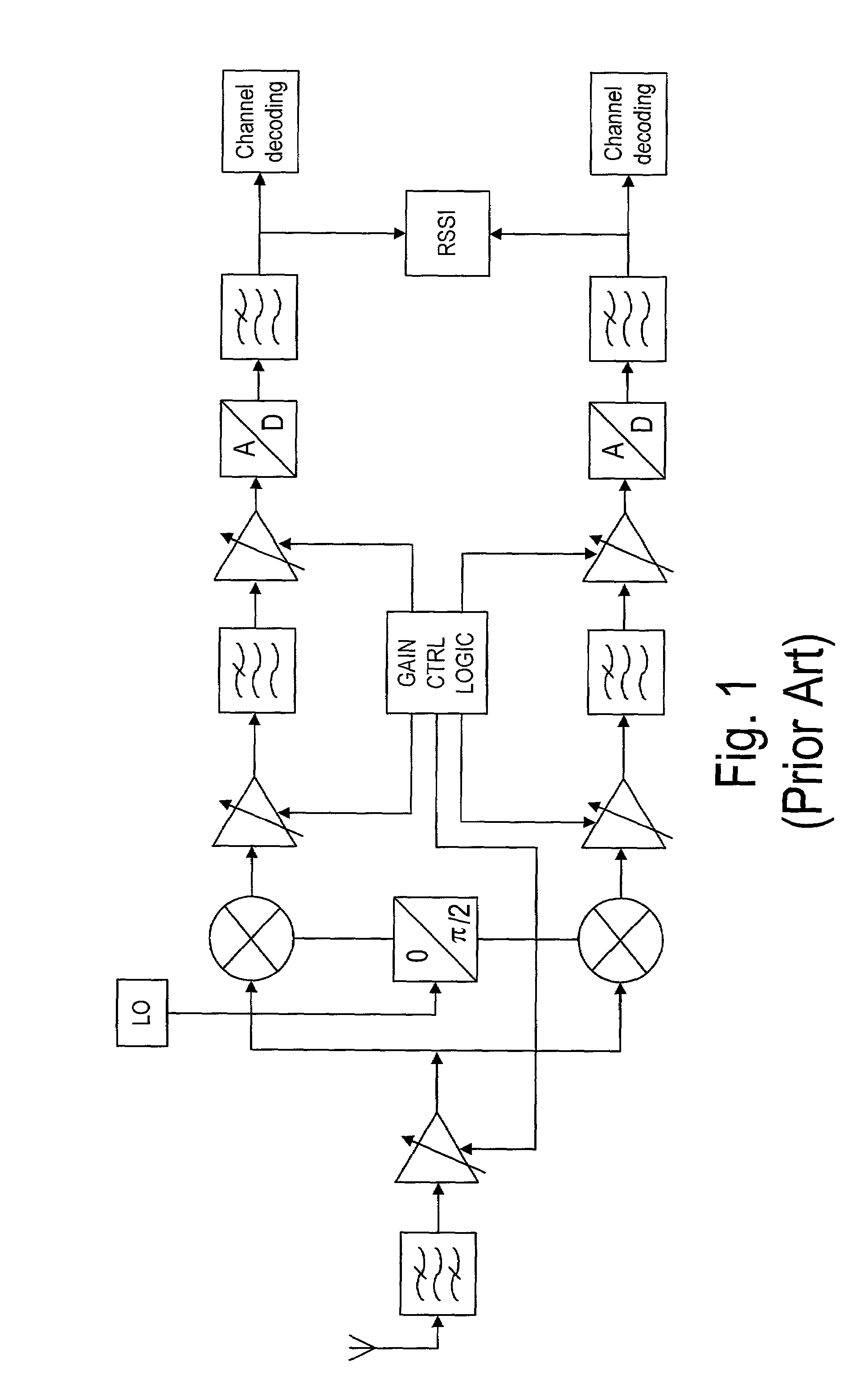
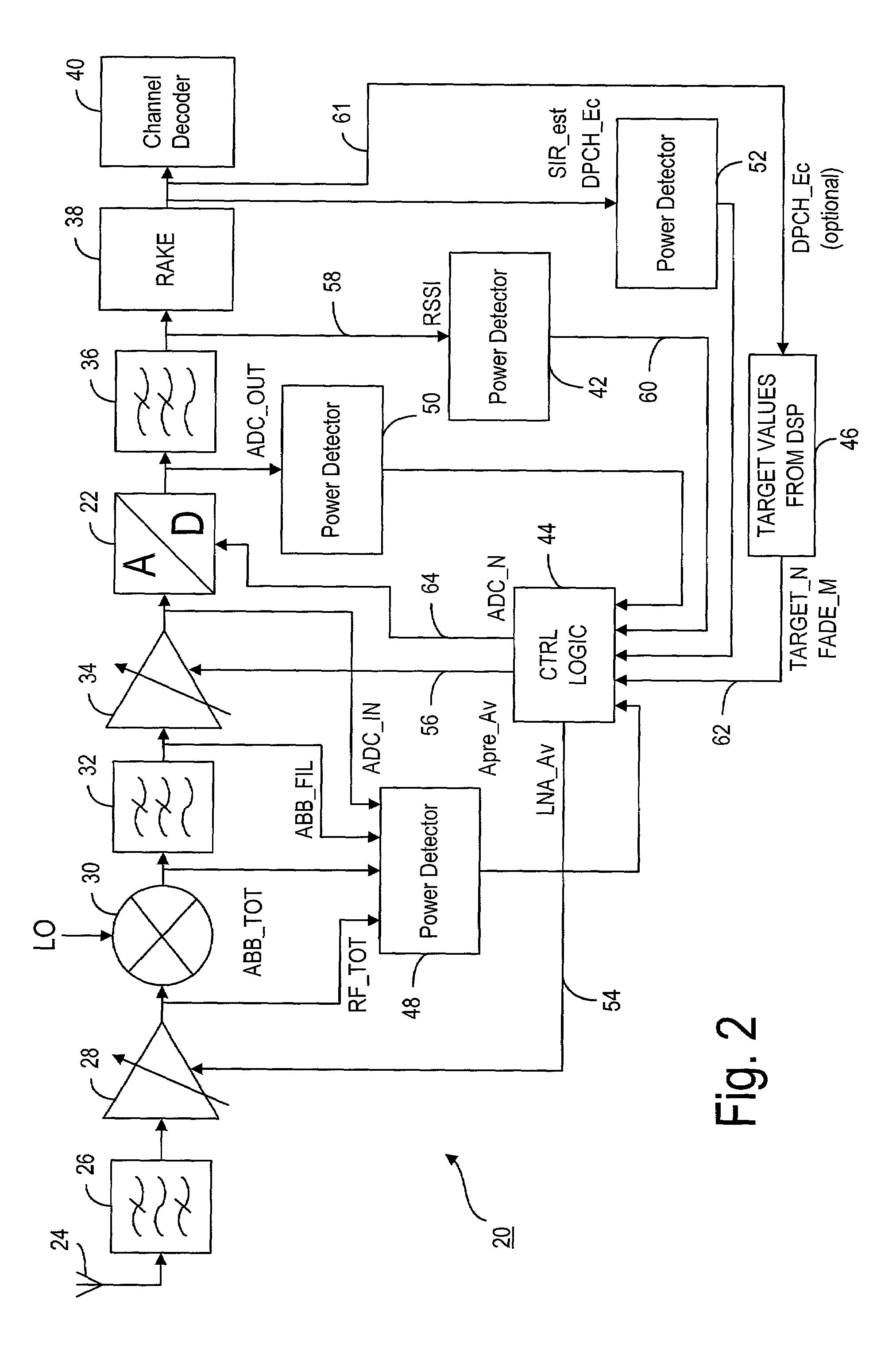
[0025]FIG. 2 is a block diagram of a radio receiver 20 with an analog-to-digital converter 22 (ADC) having dynamic range control according to the present invention. It shows a radio frequency receiver with a CDMA processing block (RAKE) 38 which is shown separately from other channel decoding functions. CDMA signal processing techniques other than RAKE can also be used in the digital architecture. Radio receiver 20 has one downconverting stage and can have several intermediate frequencies. It digitizes the signal received at antenna 24 from baseband, from any intermediate frequency, or directly from the incoming radio frequency of the associated radio frequency channel. The receiver can have in-phase and quadrature branches similar to the in-phase and quadrature branches shown in FIG. 1, which is block diagram of a conventional direct conversion receive...


PUM


Abstract

A method for continuously determining the required dynamic range for an analog-to-digital converter by determining the received signal strength and using this received signal strength value in combination with the overall dynamic range for the ADC and the target resolution of the ADC to decode a radio channel in the absence of interference, wherein the target resolution is also related to the type of decoding to be performed subsequent to analog-to-digital conversion. The method allows for a reduction in power consumption associated with the ADC, especially when the incoming signal is received with few interfering radio channels and with a relatively high signal strength. The present method can be combined with gain control and analog alert detection.

Description

TECHNICAL FIELD[0001]The present invention relates to dynamic adjustment of an analog-to-digital converter (ADC) typically for use in a radio receiver. It is particularly adapted to such dynamic adjustment where the ADC operates under fluctuating signal conditions.BACKGROUND OF THE INVENTION[0002]Analog-to-digital converters (ADCs) are well-known in the electronic art for converting an analog input signal to a digital output signal. As such, they are used in many applications including radio receivers and in particular, mobile radio receivers. Such receivers, and especially mobile receivers, typically operate where the incoming radio frequency (RF) signal fluctuates in signal strength and overall quality due to interference with adjacent radio frequency signals. Such signals, which commonly are radio frequency channels, contain desired information which is to be ultimately decoded by the radio receiver. Both the received radio frequency channel and other radio frequency transmission...

Claims


Application Information

Patent Timeline
IPC IPC(8): H04B17/00H03M1/62H04B1/10H04B1/16
CPCH03G3/3068H04B1/16H04B1/109H04B1/10
Inventor PARSSINEN, AARNOVEPSALAINEN, JUSSISEPPINEN, PAULI
Owner WSOU INVESTMENTS LLC
Why Eureka
Try Eureka