Dc-to-dc converter with flyback period detector circuit
- Summary
- Abstract
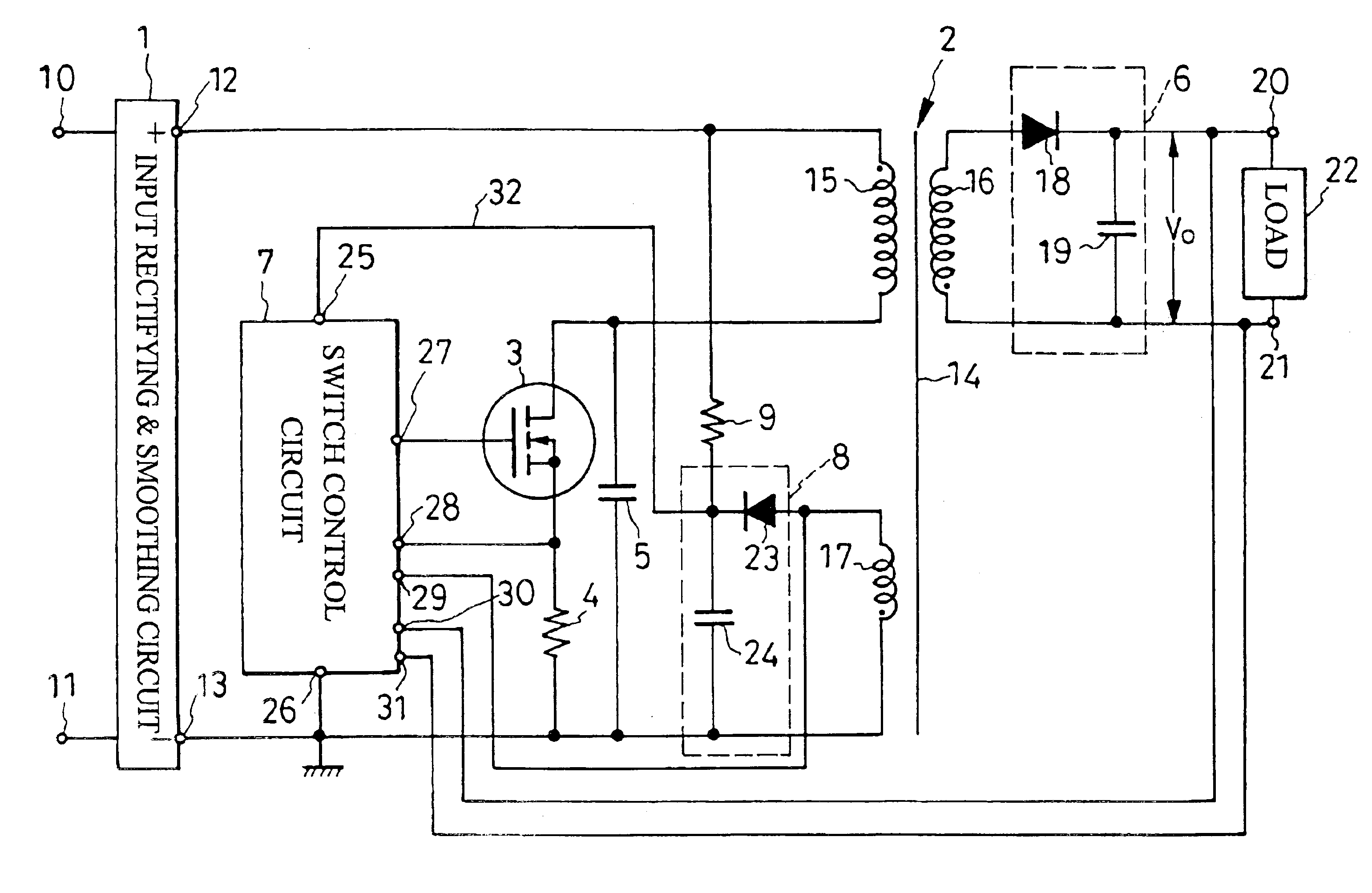
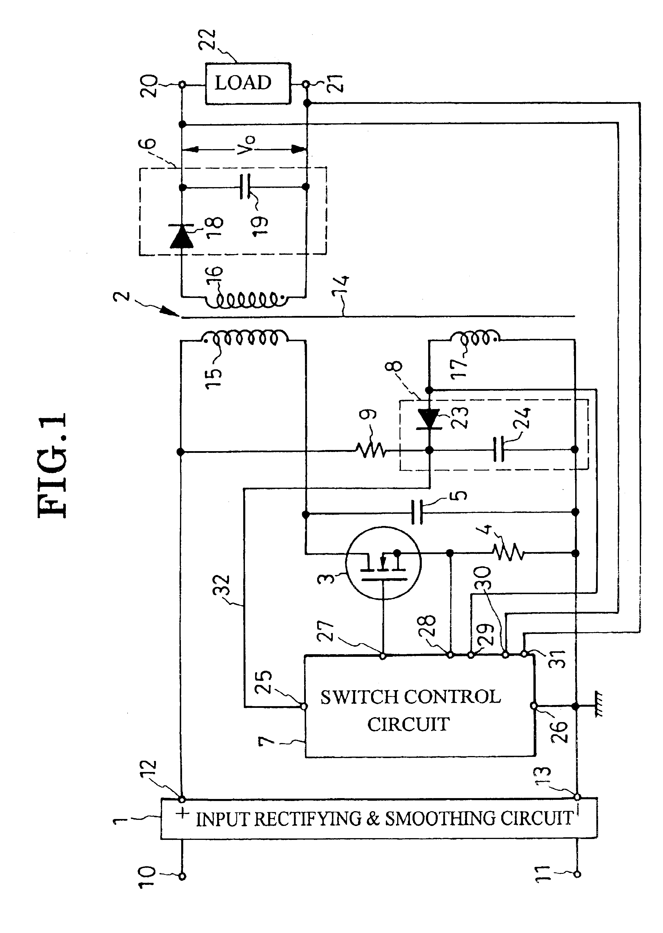
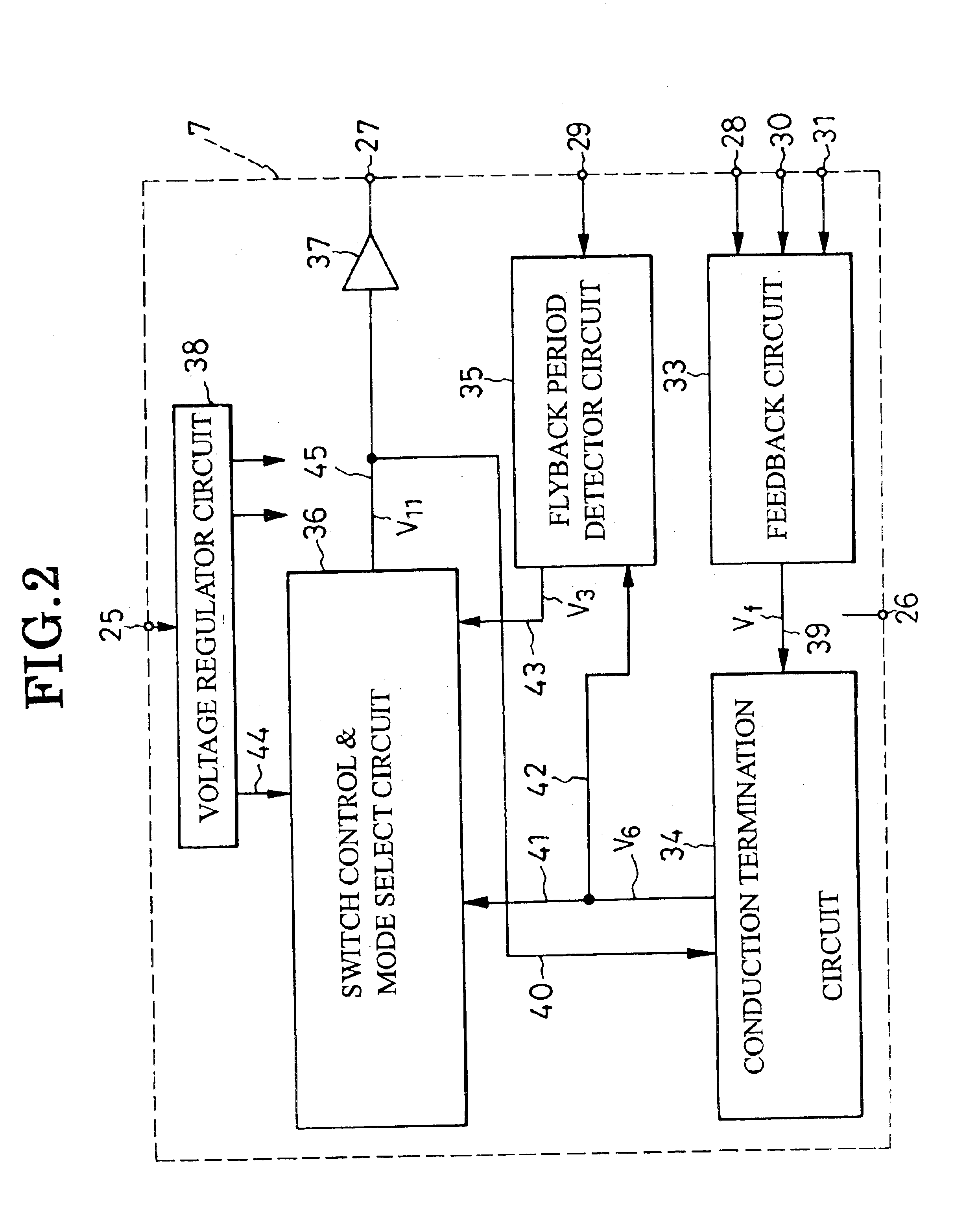
- Description
- Claims
- Application Information
AI Technical Summary
Benefits of technology
Problems solved by technology
Method used
Image

Examples
embodiment
of FIG. 14
FIG. 14 shows a modified feedback circuit 33a for use in the FIG. 1 dc-to-dc converter in substitution for the first disclosed feedback circuit 33 shown in detail in FIG. 3. The modified feedback circuit 33a broadly comprises the output voltage feedback circuit 46 and a sawtooth feedback circuit 47a. The output voltage feedback circuit 46 is of the same construction as its FIG. 3 counterpart except for the way the phototransistor 53 is coupled to the supply terminal 25.
The sawtooth feedback circuit 47a represents a substantial alteration of the sawtooth feedback circuit 47 shown in FIG. 3. Included is a capacitor 105 which is connected via a resistor 102 to the current detect terminal 28, so that the capacitor develops a voltage in proportion with the magnitude of the current through the switch 3, FIG. 1. A pnp transistor 106 has its base connected to the capacitor 105, its emitter to a voltage regulator circuit 38 via a constant-current regulator 112, and its collector gr...
PUM
 Abstract
Description
Claims
Application Information
 - Generate Ideas
- Intellectual Property
- Life Sciences
- Materials
- Tech Scout
- Unparalleled Data Quality
- Higher Quality Content
- 60% Fewer Hallucinations
Browse by: Latest US Patents, China's latest patents, Technical Efficacy Thesaurus, Application Domain, Technology Topic, Popular Technical Reports.
© 2025 PatSnap. All rights reserved.Legal|Privacy policy|Modern Slavery Act Transparency Statement|Sitemap|About US| Contact US: help@patsnap.com