Electrical-optical cable for wireless systems

a wireless system and optical cable technology, applied in the field of wireless communication systems, can solve the problems of inconvenient use of coax cables, and inconvenient installation of coax cables

Inactive Publication Date: 2007-10-25
CORNING OPTICAL COMM LLC
View PDF99 Cites 119 Cited by
  • Summary
  • Abstract
  • Description
  • Claims
  • Application Information

AI Technical Summary

Benefits of technology

[0008] One aspect of the invention is an electrical-optical cable apparatus for a wireless system. The cable includes first and second optical fibers, and an electrical power line. The cable also includes first and second electrical-optical (E / O) converter units that are optically coupled to respective opposite ends of the first and second optical fibers, and that are electrically coupled to the respective opposite ends of the electrical power line. The electrical power line provides electrical power from the first to the second E / O converter unit so that the second E / O converter unit does not need to be connected to a separate power source. Each E / O converter unit has one or more RF electrical connectors adapted to receive and / or transmit RF electrical signals. The E / O converter units are adapted to convert the RF electrical signals into RF optical signals and vice versa, so as to provide RF signal communication between the RF electrical connectors of the first and second E / O converter units via the first and second optical fibers.

Problems solved by technology

There are often constraints as to where WiFi device can be located, particularly for in-door WiFi coverage.
In many cases, the physical dimensions of the WiFi device are not suited for the WiFi box to be installed at the same location as the antenna.
While the typical coaxial cable used in a WiFi system can be quite long, the use of a long coax cable is problematic when the cable loss at the frequencies of interest is too high to maintain the needed signal quality.
Unfortunately, overcoming the cable loss problem by electrical signal amplification is limited to moderate loss levels because strong signal amplification reduces the signal-to-noise ratio (SNR).

Method used


Image

  • Electrical-optical cable for wireless systems
  • Electrical-optical cable for wireless systems
  • Electrical-optical cable for wireless systems

Examples


example method

of Operation

[0038]FIG. 5 is a schematic diagram of an example WiFi system 100 that includes an example embodiment of cable 10 of the present invention. Cable 10 is used in WiFi system 100 as a transparent ˜0 dB loss cable for operably connecting a remote antenna to a WiFi access point device. WiFi system 100 includes an RF electrical signal source 110, which in an example embodiment is an access point device or a WiFi box. RF electrical signal source 110 includes a connector 112, which is connected to connector 40B of E / O converter unit 20B of cable 10. RF electrical signal source 110 includes an electrical power cord 116 that plugs into a conventional electrical outlet 120 or other power supply. WiFi system 100 also includes a power supply 92 electrically coupled to E / O converter unit via input electrical power line 44, and is plugged into electrical outlet 120 via an electrical power cord 122. In an example embodiment, RF electrical signal source 110 is plugged into power supply 9...

example frequency

Ranges

[0053] In an example embodiment, the RF frequency range of the present invention falls between 2.4 GHz and 5.2 GHz, which covers both ISM frequency bands used in WiFi systems. These frequencies are readily obtainable with commercially available high-speed lasers, transmitters and photoreceivers. In another example embodiment, the frequency range of the present invention falls between 800 MHz and up to (a) 2.4 GHz; or (b) 5.2 GHz; or (c) 5.8 GHz. In an example embodiment, the frequency range is selected to include cellular phone services, and / or radio-frequency identification (RFID). In another example embodiment, the frequency range of the present invention covers only a narrow band of ˜200 MHz around 2.4 GHz or around a frequency between about 5.2 and about 5.8 GHz.

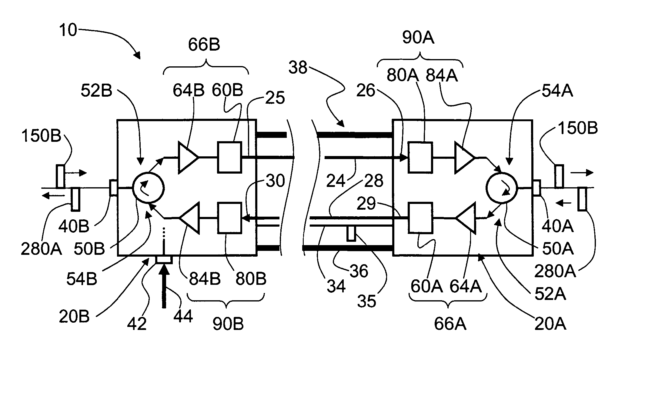
[0054] The main source of loss in cable 10 is due to the electrical-optical-electrical conversion process. In an example embodiment, this conversion loss is compensated for by amplifying the RF signals within the ...


PUM


Abstract

An electrical-optical cable for wireless system that includes two electrical-to-optical (E / O) converter units optically and electrically coupled via a cord that includes a downlink optical fiber, an uplink optical fiber, and an electrical power link. The first E / O converter receives radio-frequency (RF) electrical signals from an access point device, converts them to corresponding RF optical signals, and transmits the optical signals over the downlink optical fiber to the second E / O converter. The second E / O converter receives and converts the RF optical signals back to the original RF electrical signals. The RF electrical signals at one of the E / O converter units drive an antenna connected thereto. RF signals received by the wireless antenna are processed in a similar manner, with the optical signals being sent to the other E / O converter unit over the uplink optical fiber. The electrical-optical cable allows for the remote placement of the antenna relative to an access point device, with the antenna-side E / O converter unit power by electrical power provided by the other E / O converter unit.

Description

BACKGROUND OF THE INVENTION [0001] 1. Field of the Invention [0002] The present invention relates generally to wireless communication systems, and particularly to a cable capable of carrying both radio-frequency (RF) optical signals and electrical power from a wireless access point device to a remote antenna. [0003] 2. Technical Background [0004] Wireless communication is rapidly growing, with ever increasing demands for high-speed mobile data communication. As an example, so-called “wireless fidelity” or “WiFi” systems are being deployed in many different types of areas (coffee shops, airports, libraries, etc.) for high-speed wireless Internet access. [0005] In a WiFi system, localized wireless coverage is provided by an electronic digital RF signal transmitter / receiver device (hereinafter, “WiFi device”) that includes an access point device (also called a “WiFi box” or “wireless access point”), and an antenna connected thereto. There are often constraints as to where WiFi device c...

Claims


Application Information

Patent Timeline
Patent Type & Authority Applications(United States)
IPC IPC(8): H04B10/00
CPCG02B6/4469G02B6/4416
Inventor SAUER, MICHAEL
Owner CORNING OPTICAL COMM LLC
Why Eureka
Try Eureka