
Flexible display device and electronic device including the same

a display device and flexible technology, applied in the direction of identification means, electrical apparatus casings/cabinets/drawers, instruments, etc., can solve the problems of undesired bending deterioration of the aesthetic appearance of the device, etc., to facilitate the mounting stabilize the support of the display panel, and prevent damage to the display panel

Active Publication Date: 2020-07-28
LG DISPLAY CO LTD
View PDF23 Cites 17 Cited by
  • Summary
  • Abstract
  • Description
  • Claims
  • Application Information

AI Technical Summary

Benefits of technology

The present invention is about a flexible display screen that can be repeatedly folded and unfolded without getting damaged. This makes it easier to rework and mount the display screen in a case.

Problems solved by technology

However, in the case of a flexible display device in which an adhesive member is provided at a folding region, the display panel may be undesirably bent, or the adhesive member may peel off from the folding region.
In flexible display devices developed to date, after repeated folding and unfolding operations, the folding region is separated from other regions, and is therefore visible from the outside, leading to deterioration in the aesthetic appearance of the device.

Method used


Image

  • Flexible display device and electronic device including the same
  • Flexible display device and electronic device including the same
  • Flexible display device and electronic device including the same

Examples


first embodiment

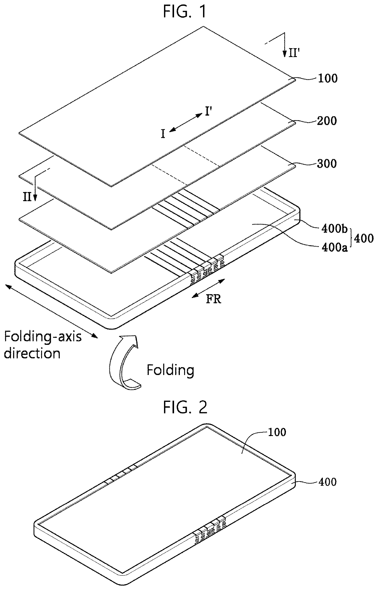
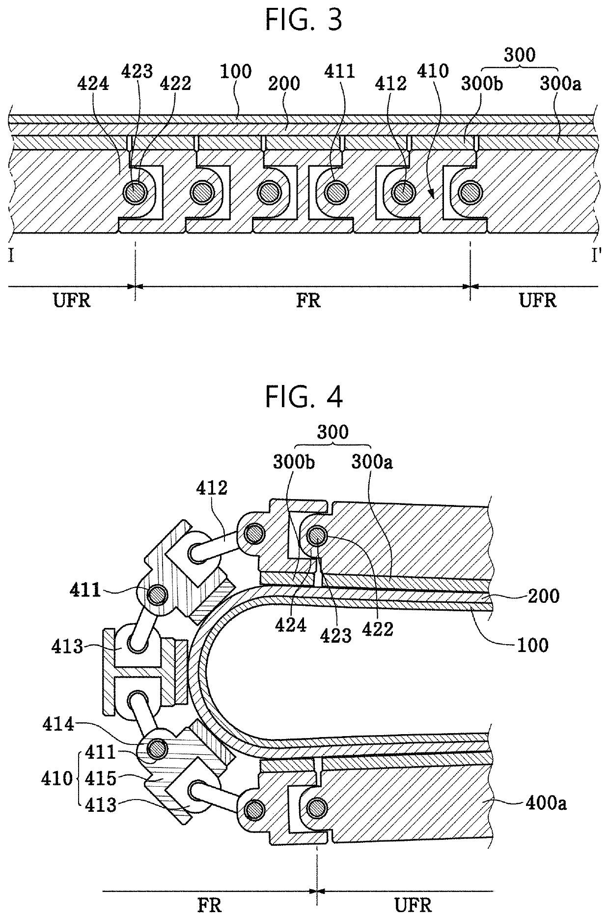
[0056]FIG. 1 is an exploded perspective view of a flexible display device according to the present disclosure. FIG. 2 is a perspective view illustrating the coupled state of the flexible display device shown in FIG. 1. FIG. 3 is a cross-sectional view taken along line I-I′ in the unfolded state of the flexible display device shown in FIG. 1. FIG. 4 is a cross-sectional view taken along line I-I′ in the state in which the flexible display device shown in FIG. 1 is folded in half about a folding axis.

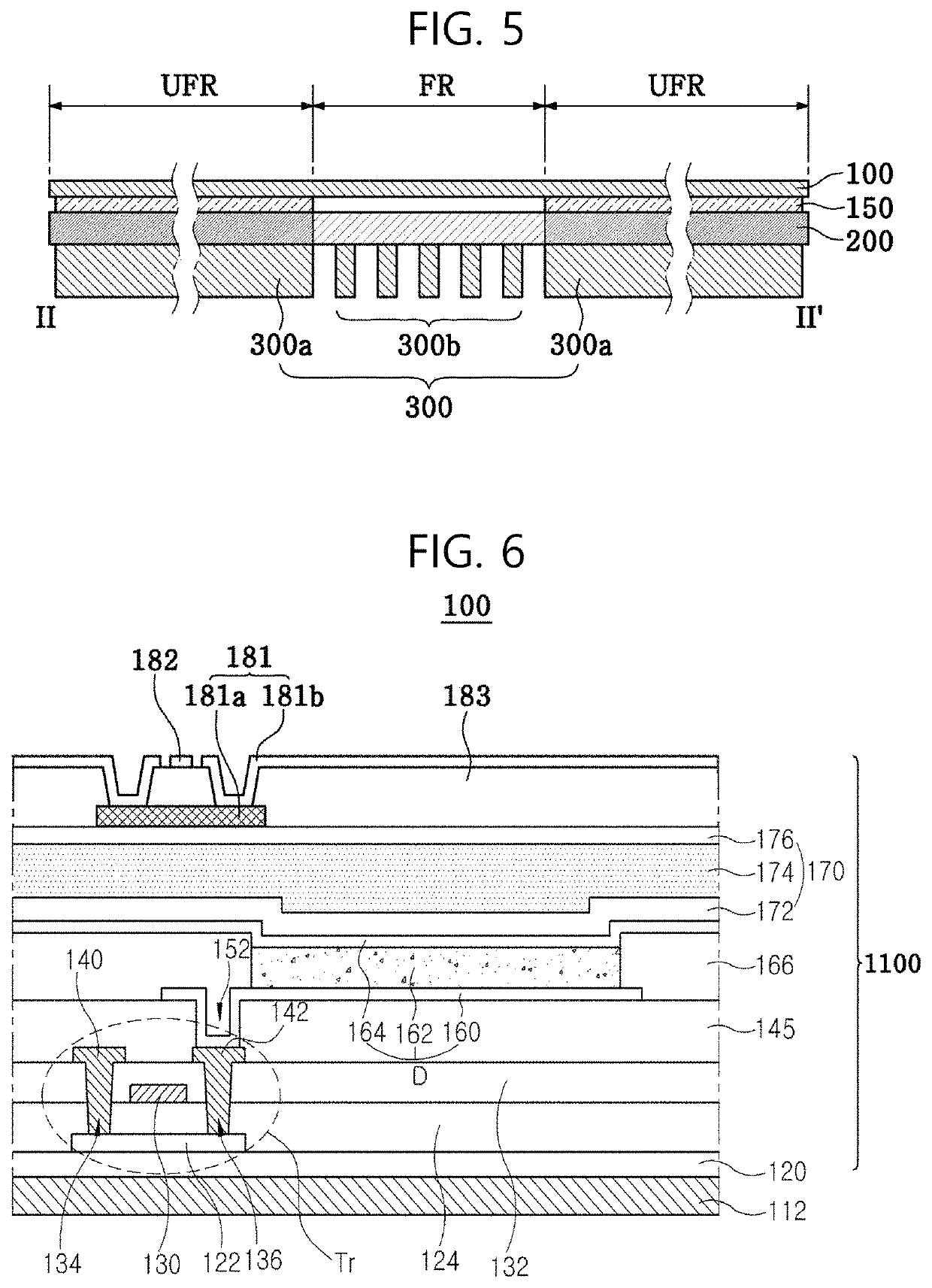
[0057]As shown in FIGS. 1 to 4, the flexible display device according to the first embodiment of the present disclosure includes a display panel 100, a lower plate 200, a magnetic body group 300, and a housing member 400, which are sequentially arranged from the top. This flexible display device according to the first embodiment of the present disclosure, as shown in FIGS. 1 to 4, is a foldable display, which can be folded such that a region thereof extending along line II-IF is folded in...

second embodiment

[0187]Hereinafter, a flexible display device will be described.

[0188]FIG. 12 is an exploded perspective view illustrating the unfolded state of the flexible display device according to the second embodiment. FIGS. 13A and 13B are cross-sectional views of a folding region and peripheral components in the unfolded state and in the folded state of the flexible display device shown in FIG. 12.

[0189]As shown in FIGS. 12 to 13B, the flexible display device according to the second embodiment differs from the flexible display device according to the first embodiment in that the housing member 400 is divided into two units in the folding region FR, each unit including a gear shaft 520, a support frame 450, and a gear 510 having gear teeth formed around the gear shaft 520, and in that the housing member 400 further includes a hinge member 500 for accommodating the gear 510 and the gear shaft 520 and connecting the two divided units. The gear 510 of one of the two units and the gear 510 of th...


PUM


Abstract

A flexible display device and an electronic device including the same are disclosed. The flexible display device includes a magnetic body group, which is adhered to a lower plate provided under a display panel by the force of magnetic attraction. Therefore, the flexible display device has improved reliability in spite of frequent folding and unfolding operations and is capable of facilitating a rework process.

Description

CROSS-REFERENCE TO RELATED APPLICATION(S)[0001]This application claims the benefit of Korean Patent Application No. 10-2017-0096363, filed on Jul. 28, 2017, which is hereby incorporated by reference as if fully set forth herein.BACKGROUNDTechnical Field[0002]The present disclosure relates to a flexible display device, and more particularly to a flexible display device that has improved reliability in spite of frequent folding and unfolding operations and facilitates a rework process and to an electronic device including the same.Description of the Related Art[0003]An image display device, which realizes various pieces of information on a screen, is a core technology of the information and communication age, and is being developed in the direction of becoming thinner, lighter, more portable, and having higher performance. As a flat panel display device that is capable of overcoming the problems of disadvantageous weight and volume of a cathode ray tube (CRT), for example, an organic ...

Claims


Application Information

Patent Timeline
Patent Type & Authority Patents(United States)
IPC IPC(8): H05K5/00H05K5/02H01L51/52H05K1/14G06F1/16H05K1/02H01L51/00H05K9/00H01L27/32H10K99/00
CPCH05K1/028G06F1/1652H01L51/5237H05K1/147H05K5/0086H05K5/0017G06F1/1641G06F1/1601H05K5/0226H01L2251/5338H01L51/0097H05K2201/056H05K9/0054H01L27/323H01L27/3244G06F2203/04102G09F9/301H10K59/12H10K77/111H10K2102/311H10K59/87H10K50/84G06F1/1616H10K59/40
Inventor KIM, JUN-HYUNGKIM, TAE-WOOPARK, JUNG-KYU
Owner LG DISPLAY CO LTD
Learn More