Mount structure for an aircraft ancillary engine unit

a technology for ancillary engines and mounting structures, which is applied in the direction of machines/engines, machine supports, transportation and packaging, etc., can solve the problems of increasing the risk of bracket failure by metal fatigue, increasing the risk of bracket failure, and reducing the compliance in critical directions. , the effect of reducing the peak stress level of the stru

Active Publication Date: 2020-08-04
ROLLS ROYCE PLC
View PDF38 Cites 0 Cited by
  • Summary
  • Abstract
  • Description
  • Claims
  • Application Information

AI Technical Summary

Benefits of technology

[0008]Thus, rather than the strengthening the struts by adding material to the mount structure but thereby increasing the weight of the structure, the struts are configured in such a way as to have a reduced compliance in critical directions. In this way peak stress levels in the struts can be reduced while allowing the struts to cope with thermal growth of the housing of the ancillary engine unit. The containment bracket then helps to increase the stiffness of the mount structure in other directions. In particular, this increased stiffness can increase the first natural resonance frequency of the structure such that it is greater than the first order shaft vibration frequency of the high pressure shaft of the engine.

Problems solved by technology

A problem arises, however, in that the thermal cycling imposed on the ancillary units and brackets by the operation of the engine can lead to the imposition of substantial cyclic stresses on the units and brackets because of differential thermal expansion effects.
However, aluminium alloy does not generally have sufficient strength at high temperature to be used to form the brackets, as these have to make direct contact with hot parts of the engine assembly.
This tensile stress poses a significant risk where the bracket is subjected to cycles of temperature change over multiple engine operations, as the cycles of temperature change directly translate to cycles of stress in the bracket, increasing the risk of bracket failure by metal fatigue.
However, both these options undesirably increase the weight of the bracket.
Also, reducing stresses at one part on the bracket may simply move the problem to another part of the bracket.
The struts may have shapes that are difficult or uneconomical to form by other, more traditional, manufacturing techniques.

Method used


Image

  • Mount structure for an aircraft ancillary engine unit
  • Mount structure for an aircraft ancillary engine unit
  • Mount structure for an aircraft ancillary engine unit

Examples


Embodiment Construction

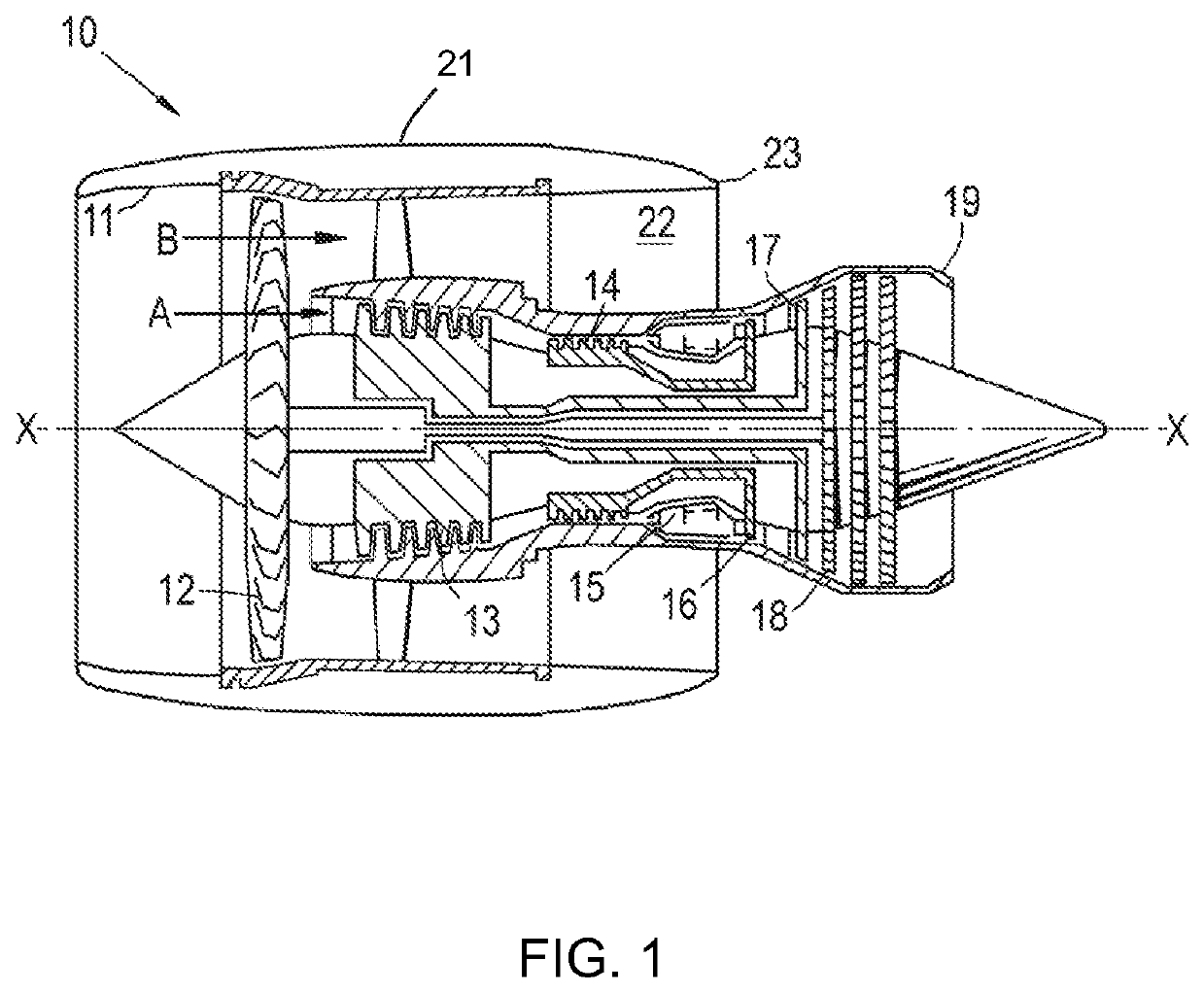
[0031]With reference to FIG. 1, a ducted fan gas turbine engine incorporating the invention is generally indicated at 10 and has a principal and rotational axis X-X. The engine comprises, in axial flow series, an air intake 11, a propulsive fan 12, an intermediate pressure compressor 13, a high-pressure compressor 14, combustion equipment 15, a high-pressure turbine 16, an intermediate pressure turbine 17, a low-pressure turbine 18 and a core engine exhaust nozzle 19. A nacelle 21 generally surrounds the engine 10 and defines the intake 11, a bypass duct 22 and a bypass exhaust nozzle 23.

[0032]During operation, air entering the intake 11 is accelerated by the fan 12 to produce two air flows: a first air flow A into the intermediate-pressure compressor 13 and a second air flow B which passes through the bypass duct 22 to provide propulsive thrust. The intermediate-pressure compressor 13 compresses the air flow A directed into it before delivering that air to the high-pressure compres...


PUM

PropertyMeasurementUnit
temperaturesaaaaaaaaaa
temperatureaaaaaaaaaa

Abstract

A mount structure for mounting an ancillary engine unit to a gas turbine engine is provided. The mount structure has plural elongate struts which each extend from a connector portion at one end of the strut to a fastening portion at the other end of the strut. The housing of the ancillary engine unit is formed of a first material having a first coefficient of thermal expansion, and the elongate struts are formed of a second material having a second coefficient of thermal expansion. Each elongate strut extends away from its connector portion in a direction which is crosswise to the direction of the hypothetical differential thermal strain at that connector portion. The mount structure further has a containment bracket which is configured to contain each connector portion.

Description

CROSS-REFERENCE TO RELATED APPLICATION[0001]This application is based upon and claims the benefit of priority from British Patent Application No. 1621455.3 filed 16 Dec. 2016, the entire contents of which are incorporated herein.BACKGROUND1. Field of the Disclosure[0002]The present invention relates to a mount structure for mounting an ancillary engine unit to a gas turbine engine.2. Description of the Related Art[0003]Gas turbine engine ancillary units often require brackets in order to be mounted to and space from relatively hot parts of the engine assembly, such as core engine casings. A problem arises, however, in that the thermal cycling imposed on the ancillary units and brackets by the operation of the engine can lead to the imposition of substantial cyclic stresses on the units and brackets because of differential thermal expansion effects.[0004]In particular, the housings of engine ancillary units are often formed of aluminium alloy, which has a coefficient of thermal expan...

Claims


Application Information

Patent Timeline
Patent Type & Authority Patents(United States)
IPC IPC(8): F02C7/32F02C7/20F01D25/26B33Y80/00F01D25/28B64D41/00F16M13/02
CPCF01D25/26F01D25/28F02C7/32F02C7/20B33Y80/00F16M13/02F05D2250/41F05D2260/941F05D2300/50212F05D2220/50F05D2230/31F05D2300/174F05D2300/173B64D2041/002F05D2240/91F05D2220/323
Inventor YANG, RONGISLES, DAVID
Owner ROLLS ROYCE PLC
Why Eureka
Try Eureka