Midsole structure for a shoe

a technology of midsole and shoe, which is applied in the field of midsole structure for shoes, can solve problems such as loss of ride feeling during running, and achieve the effects of improving cushioning properties maintaining stability at the time of impacting the ground, and reducing hardness

Active Publication Date: 2020-08-18
MIZUNO CORPORATION
View PDF22 Cites 4 Cited by
  • Summary
  • Abstract
  • Description
  • Claims
  • Application Information

AI Technical Summary

Benefits of technology

[0016]As above-mentioned, according to the midsole structure for a shoe of the present invention, since on opposite sides of the heel region, a thickness of one midsole of a greater hardness is made greater than a thickness of another midsole of a smaller hardness, a lateral leaning at the time of impacting the ground can be prevented and stability at the time of impacting the ground can be maintained. Also, since in the central part of the heel region, a thickness of another midsole of a smaller hardness is made greater than a thickness of one midsole of a greater hardness, cushioning property at the time of impacting the ground can be improved. Moreover, since the boundary surface between one midsole and another midsole does not appear on the top surface of the midsole structure, a foot sole of a shoe wearer will not contact the boundary surface between the two midsole layers of a hardness difference, such that thereby the shoe wearer does not feel uncomfortable at his / her foot sole thus enhancing ride feeling during running.

Problems solved by technology

Thereby, he / she may feel discomfort to the foot sole thus losing ride feeling during running.

Method used


Image

  • Midsole structure for a shoe
  • Midsole structure for a shoe
  • Midsole structure for a shoe

Examples


first alternative embodiment

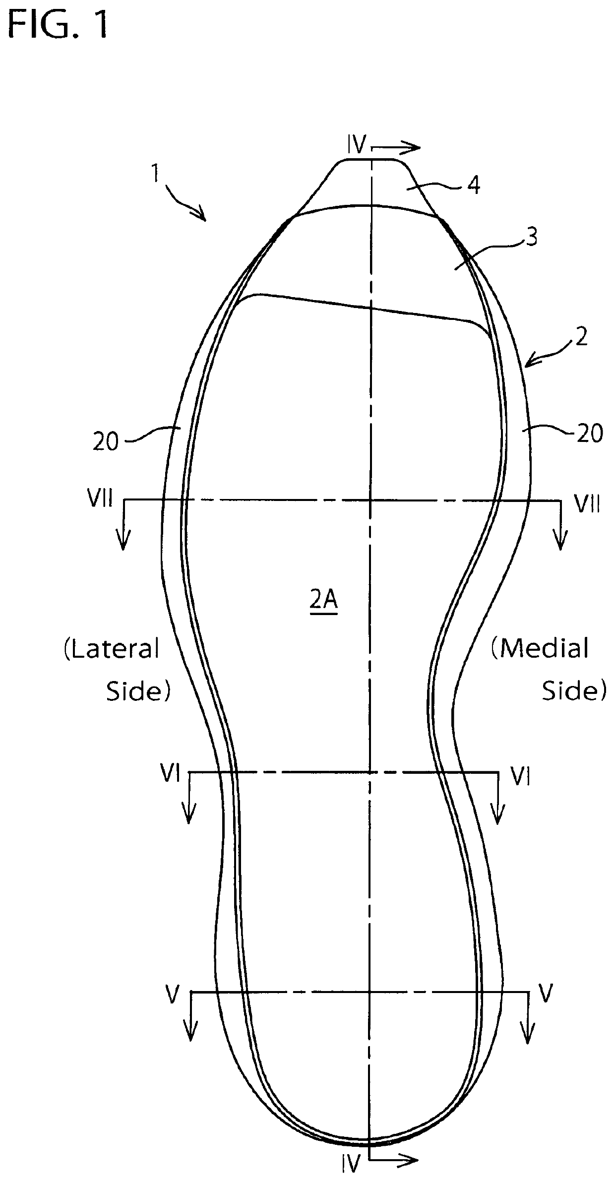
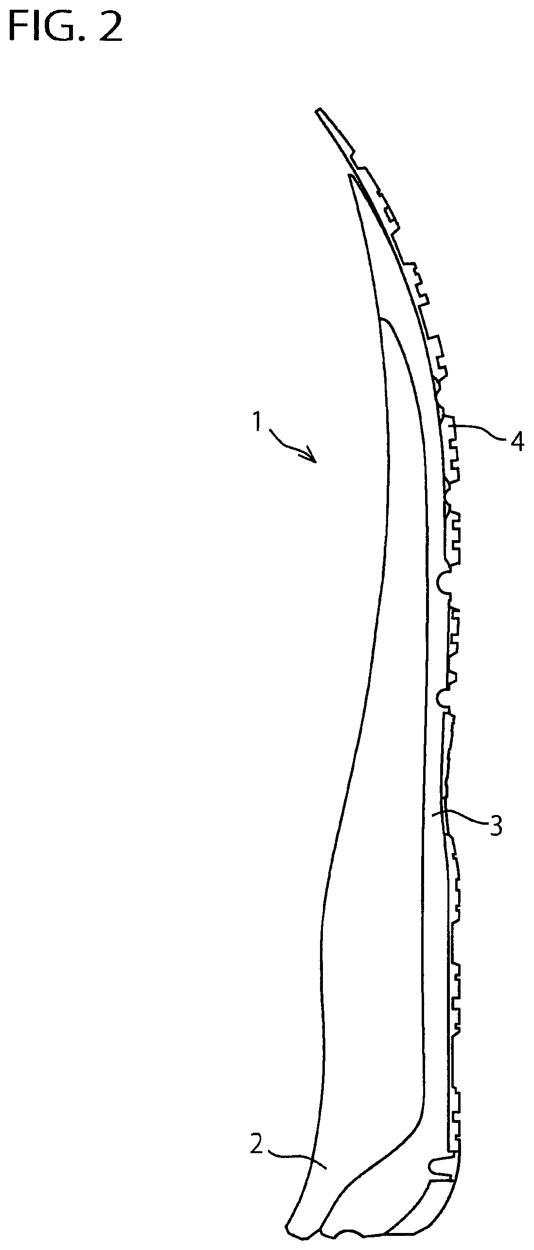
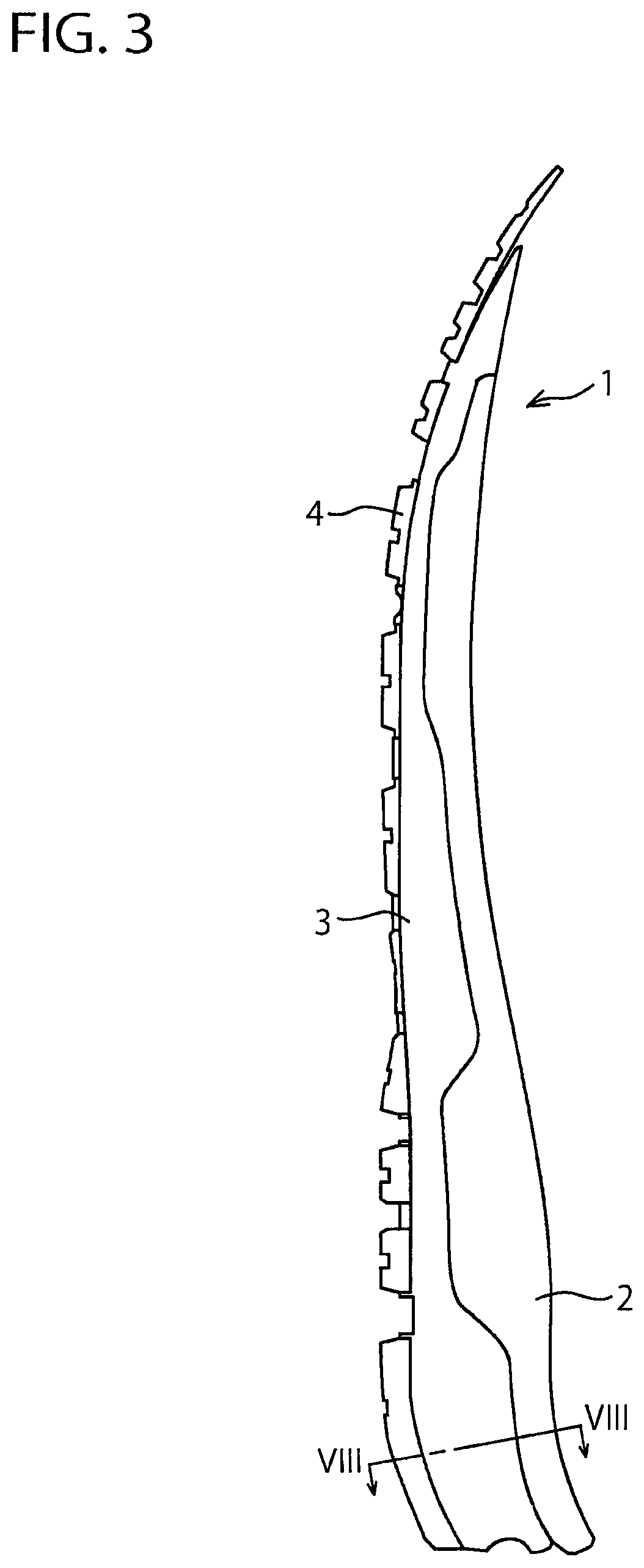
[0061]In the above-mentioned embodiment, an example in which the lower midsole 3 extends longitudinally from the heel region through the tread region to the toe portion (i.e. a full-length type) was shown, but application of the present invention is not limited to such an embodiment. FIGS. 9 to 17 show a first alternative embodiment of the present invention.

[0062]As shown in FIGS. 9 to 12, the lower midsole 3 is disposed at the heel region. The upper midsole 2 extends longitudinally from the heel region through the tread region to the toe portion. That is, in this exemplification, the heel region has a two-layer structure formed of the upper midsole 2 and the lower midsole 3 and the other regions have a single-layer structure of the upper midsole 2. A front end edge portion 3a of the lower midsole 3 may extend to a rear end portion of the plantar arch region and the front end edge portion 3a may have a different shape other than that shown in FIG. 9. At medial and lateral rear end p...

second alternative embodiment

[0071]In the above-mentioned embodiment, an example in which the lower midsole 3 extends longitudinally from the heel region through the tread region to the toe portion (i.e. a full-length type) was shown, but application of the present invention is not limited to such an embodiment. FIGS. 18 to 25 show a second alternative embodiment of the present invention.

[0072]As shown in FIGS. 18 to 21, the lower midsole 3 is disposed at a region extending from the heel region to the plantar arch region. The upper midsole 2 extends longitudinally from the heel region through the tread region to the toe portion. That is, in this exemplification, the heel region and the plantar arch region have a two-layer structure formed of the upper midsole 2 and the lower midsole 3 and the other regions have a single-layer structure of the upper midsole 2. Also, at a region extending from a lateral rear end portion through a medial rear end portion to the medial side of the heel region, an outer circumferent...

third alternative embodiment

[0082]In the above-mentioned embodiment and first and second alternative embodiments, an example in which the midsole structure 1 is formed of two layers of the high-hardness upper midsole 2 and the low-hardness lower midsole 3 was shown, but in the present invention, the midsole structure 1 may be formed of three or more layers of the midsoles.

Another Variant

[0083]The above-mentioned embodiment and respective variants are to be considered in all respects only as illustrative of the present invention and not restrictive. Those skilled in the art to which the invention pertains may make various modifications and other embodiments employing the principles of this invention without departing from its spirit or essential characteristics particularly upon considering the foregoing teachings even when there are no explicit descriptions in this specification.

Other Applications

[0084]In the above-mentioned embodiment, a midsole structure for a running shoe was taken as an example, but applic...


PUM

PropertyMeasurementUnit
areaaaaaaaaaaa
stabilityaaaaaaaaaa
hardnessaaaaaaaaaa

Abstract

A midsole structure for a shoe not only maintains stability at the time of impacting the ground and improves cushioning property but also eliminates discomfort to a foot sole and improves ride feeling during running. The midsole structure (1) comprises at least two midsoles provided at a heel region of the shoe and having a hardness difference. On opposite sides of the heel region, an upper midsole (2) of a greater hardness has a thickness greater than a thickness of a lower midsole (3) of a smaller hardness. In a central part of the heel region, the lower midsole (3) of a smaller hardness has a thickness greater than a thickness of the upper midsole (2) of a greater hardness. Boundary surfaces (2B, 3A) between the upper midsole (2) and the lower midsole (3) do not appear on a top surface of the midsole structure (1) (that is, a foot sole contact surface (2A) of the upper midsole (2)).

Description

TECHNICAL FIELD[0001]The present invention relates generally to a midsole structure for a shoe, and more particularly, to an improved midsole structure that can not only maintain stability at the time of impacting the ground and improve cushioning property but also eliminate discomfort to a foot sole and improve ride feeling during running.BACKGROUND ART[0002]As a midsole structure for a shoe, for example, Japanese Patent Application Publication No. 2012-515621 discloses a midsole structure that comprises a shell having a central concavity formed inside an outer circumferential edge portion and an insert to be inserted into the central concavity of the shell (see paras. [0021], [0024], [0036] and FIGS. 2 to 6). Also, Japanese Patent Application Publication No. 2013-529535 discloses a midsole structure that comprises a main midsole having a slope portion, an upper midsole disposed on an upper side of the main midsole, and a lower midsole disposed on a lower side of the main midsole (...

Claims


Application Information

Patent Timeline
Patent Type & Authority Patents(United States)
IPC IPC(8): A43B13/18A43B13/22A43B7/14A43B13/04A43B13/12
CPCA43B13/188A43B13/122A43B7/144A43B13/186A43B7/143A43B13/223A43B13/04A43B13/127
Inventor IUCHI, KAZUNORIDAZAI, TATSUYATAKAHASHI, YOSHITAKATAKESHITA, TAKESHI
Owner MIZUNO CORPORATION
Why Eureka
Try Eureka