Pad supporting frame

a technology for supporting frames and pads, applied in stamping, metal working apparatuses, printing, etc., can solve the problem that the carrier board supported by the tabletop cannot be deformed, and achieve the effect of reducing the cutting quality of the pad and being easy to deform

Active Publication Date: 2020-08-18
SUN SAME ENTERPRISES
View PDF5 Cites 0 Cited by
  • Summary
  • Abstract
  • Description
  • Claims
  • Application Information

AI Technical Summary

Benefits of technology

[0009]The objective of the invention is to provide a pad supporting frame that can solve the shortcoming that the delivery volume and the mold of the conventional pad supporting frame are large, the carrier board of the conventional pad supporting frame is easily deformed, and the cutting quality of the pad is decreased.
[0012]The supporting structure is detachably disposed on the bottom surface of the carrier board. The supporting structure and the carrier board are independent components. Molds of the carrier board and the supporting structure are made separately for decreasing the volumes of the molds. For delivery, the supporting structure is detached from the carrier board in each pad supporting frame. The detached supporting structures and the carrier boards can be stacked separately for decreasing the delivery volume of the pad supporting frame. A pad can be disposed on the carrier board of the pad supporting frame. For cutting, the supporting structure is detached from the carrier board. The carrier board is directly disposed on a tabletop. The bottom surface of the carrier board completely contacts the tabletop. The carrier board supported by the tabletop cannot be deformed for improving the cutting quality of the pad.

Problems solved by technology

The carrier board supported by the tabletop cannot be deformed for improving the cutting quality of the pad.

Method used


Image

  • Pad supporting frame
  • Pad supporting frame
  • Pad supporting frame

Examples


Embodiment Construction

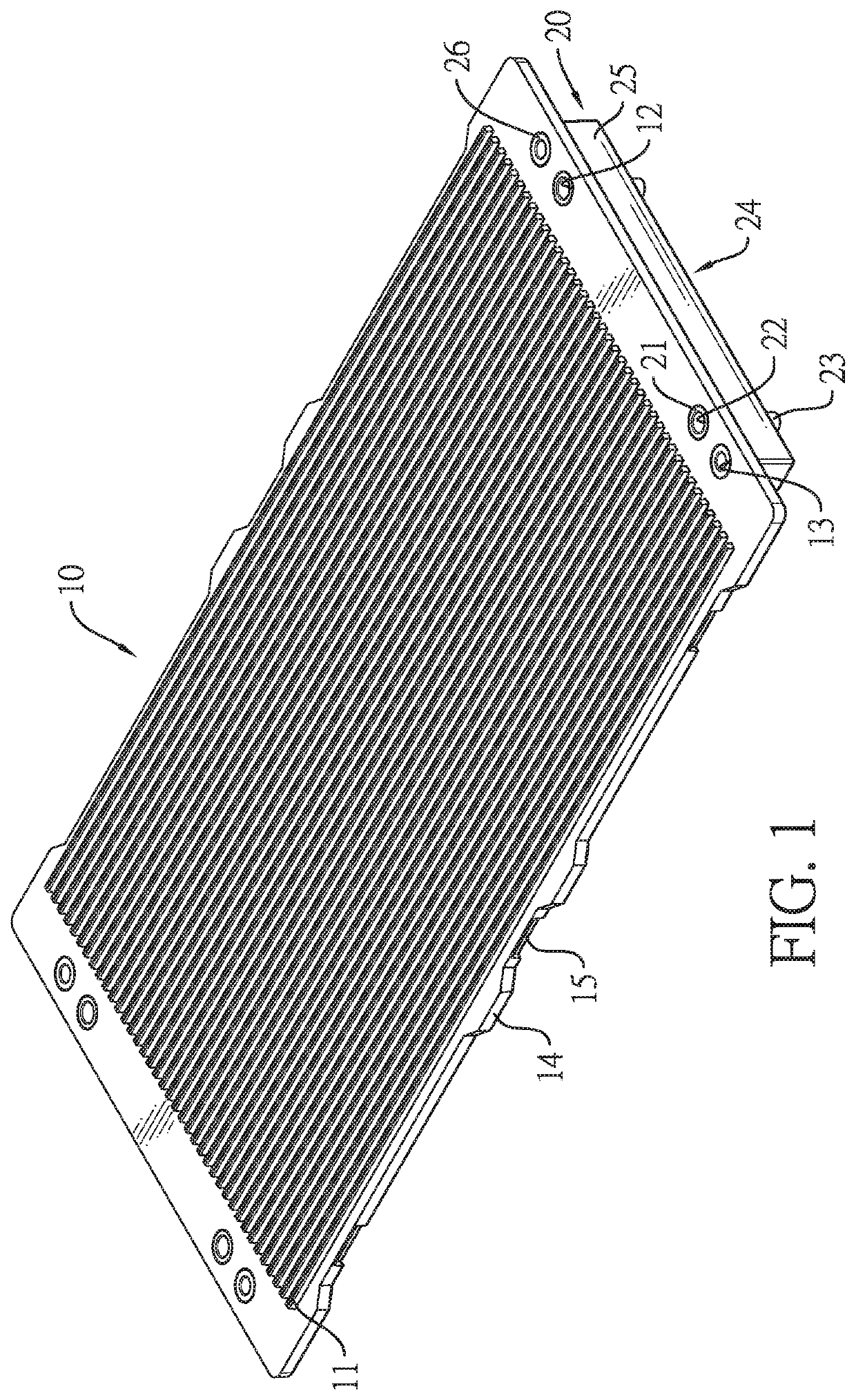
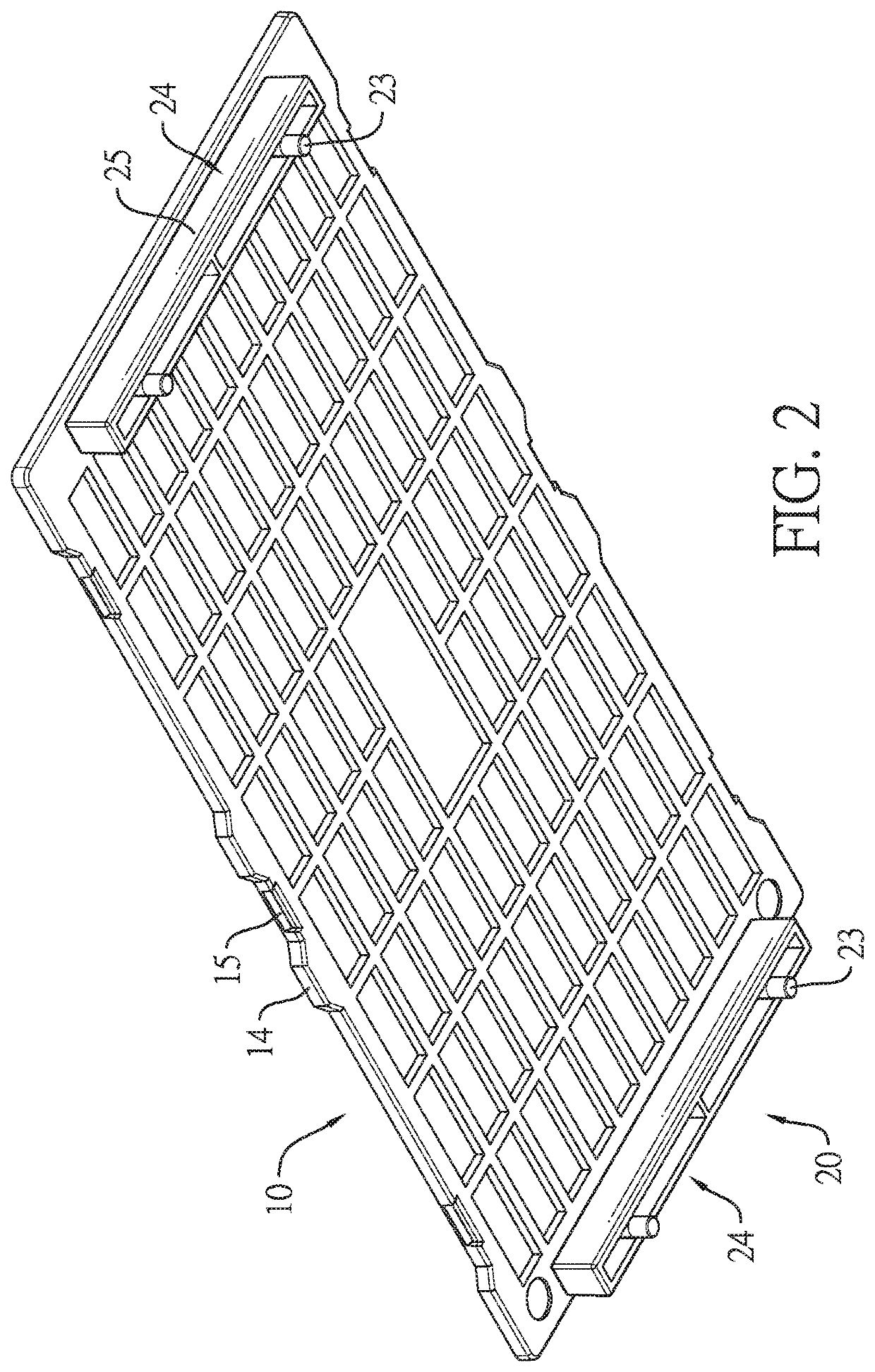
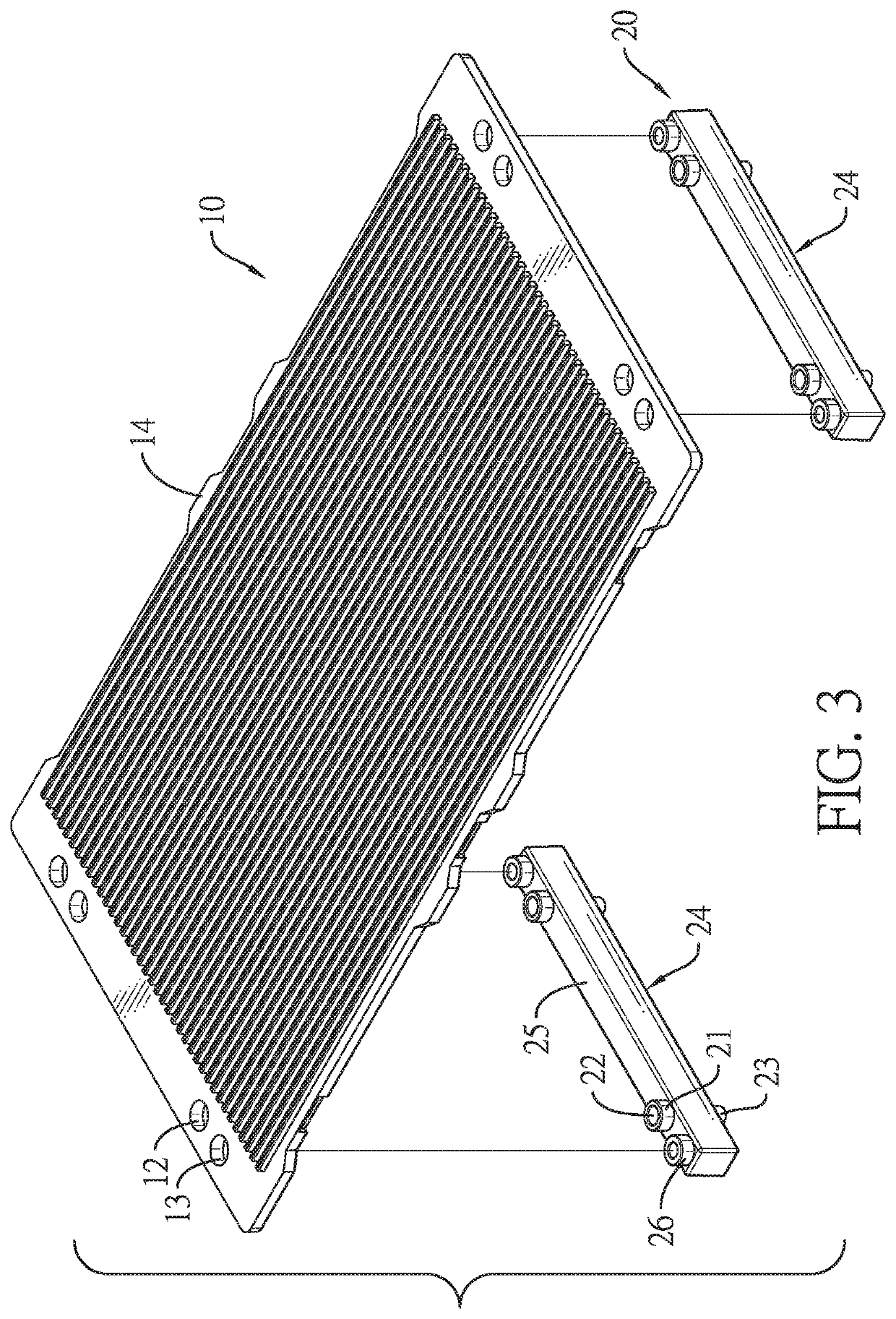
[0029]With reference to FIGS. 1 and 3, a pad supporting frame in accordance with the present invention comprises a carrier board 10 and a supporting structure 20.

[0030]The carrier board 10 has a top surface, a bottom surface, multiple bars 11, and multiple connecting holes 12. The bars 11 are formed on and protrude out of the top surface of the carrier board 10 at spaced intervals. The connecting holes 12 are formed through the top surface and the bottom surface of the carrier board 10.

[0031]The supporting structure 20 is detachably disposed on the carrier board 10, is located on the bottom surface of the carrier board 10, and has multiple connecting protrusions 21, multiple retaining holes 22, and multiple retaining protrusions 23. The connecting protrusions 21 are respectively inserted into the connecting holes 12. The retaining holes 22 are formed on top surfaces of the connecting protrusions 21, respectively. The retaining protrusions 23 are formed on bottom surfaces of the conn...


PUM


Abstract

A pad supporting frame has a carrier board and a supporting structure. The supporting structure is detachably disposed on the carrier board. The supporting structure is detachably disposed on the bottom surface of the carrier board. In delivery, the carrier board and the supporting structure can be stacked separately for increasing the utilization of the delivery space. Molds of the carrier board and the supporting structure can be made separately for decreasing the volumes of the molds. For cutting a pad disposed on the carrier board, the carrier board can be directly disposed on the tabletop. The carrier board will not be deformed and the cutting quality of the pad is improved.

Description

[0001]This application claims the benefit of Taiwan patent application No. 108201120, filed on Jan. 24, 2019.BACKGROUND OF THE INVENTION1. Field of the Invention[0002]The present invention relates to a pad supporting frame, and more particularly to a pad supporting frame that is applied to carry a pad and is detachable for improving a cutting quality of the pad.2. Description of Related Art[0003]With reference to FIGS. 11 and 12, a conventional pad supporting frame is an integrated component and has a carrier board 90 and four supporting feet 91. The carrier board 90 has a top surface, a bottom surface, multiple bars 92, and four retaining holes 93. The bars 92 protrude out of the top surface of the carrier board 90 at spaced intervals. The four retaining holes 93 are formed on the top surface of the carrier board 90 adjacent to four corners of the carrier board 90, respectively. The four supporting feet 91 protrude out of the bottom surface of the carrier board 90, and are respecti...

Claims


Application Information

Patent Timeline
Patent Type & Authority Patents(United States)
IPC IPC(8): B26D7/20B26D7/01B41K1/00
CPCB26D7/01B41K1/00B26D7/20
Inventor SHIH, WEN JER
Owner SUN SAME ENTERPRISES
Why Eureka
Try Eureka