Fog development for digital offset printing applications

a digital offset printing and fog development technology, applied in the field of marking and printing systems, can solve the problems of problematic use of scanning beam imagers, laser power consumption accounting for the majority of the total power consumption of the whole system,

Active Publication Date: 2020-08-18
XEROX CORP
View PDF3 Cites 5 Cited by
  • Summary
  • Abstract
  • Description
  • Claims
  • Application Information

AI Technical Summary

Problems solved by technology

Due to the need to evaporate the fountain solution, in the imaging module, power consumption of the laser accounts for the majority of total power consumption of the whole system.
In addition, cross-process width requirements are on the order of 36 inches, which makes the use of a scanning beam imager problematic.

Method used


Image

  • Fog development for digital offset printing applications
  • Fog development for digital offset printing applications
  • Fog development for digital offset printing applications

Examples


Embodiment Construction

[0014]Exemplary embodiments are intended to cover all alternatives, modifications, and equivalents as may be included within the spirit and scope of the composition, apparatus and systems as described herein.

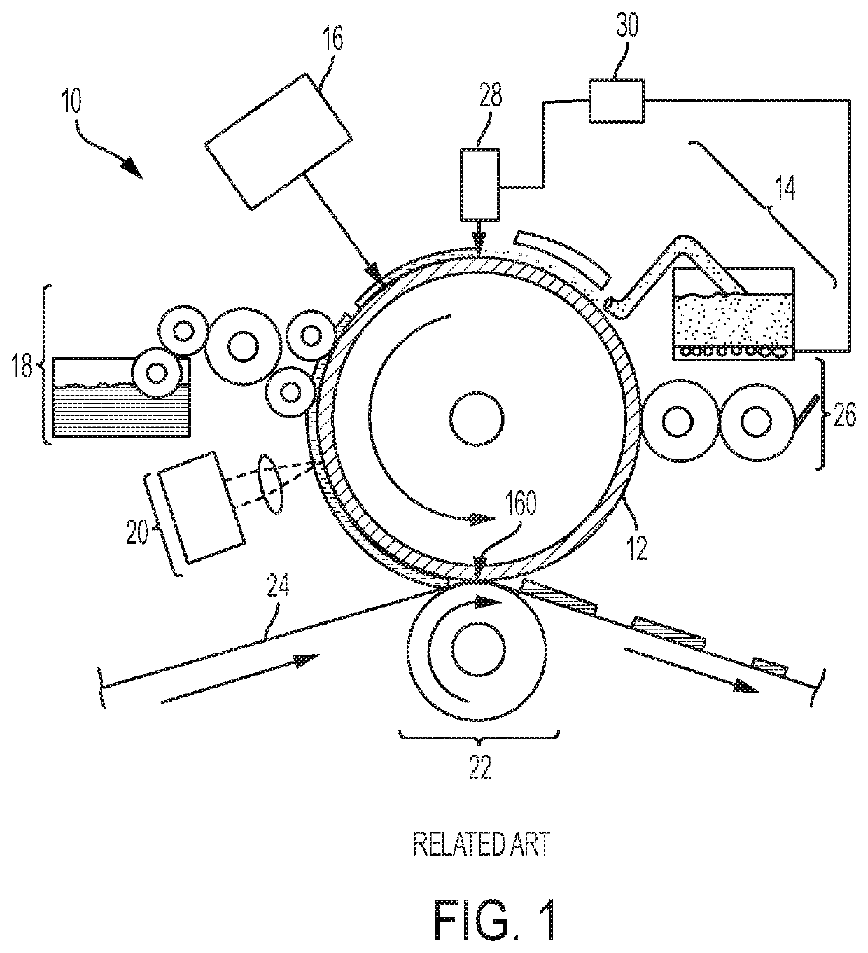
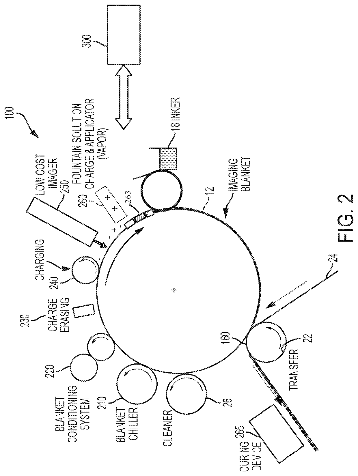
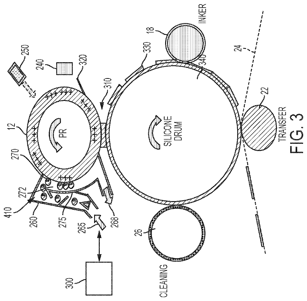
[0015]A more complete understanding of the processes and apparatuses disclosed herein can be obtained by reference to the accompanying drawings. These figures are merely schematic representations based on convenience and the ease of demonstrating the existing art and / or the present development, and are, therefore, not intended to indicate relative size and dimensions of the assemblies or components thereof. In the drawing, like reference numerals are used throughout to designate similar or identical elements.

[0016]In one aspect, an ink-based digital printing system useful for ink printing comprising: an imaging member configured for carrying a fountain solution image on the imaging member; an image forming unit that forms an electrostatic charge image of a first polarity on the ...


PUM


Abstract

Ink-based digital printing systems useful for ink printing include a photoreceptor layer configured to receive a layer of liquid immersion fluid. The liquid immersion fluid includes dampening fluid, dispersed gas particles, and charge directors that impart charge to the solid particles. The photoreceptor surface is charged to a uniform potential, and selectively discharged using an ROS according to image data to form an electrostatic latent image. The charged liquid immersion fluid adheres to portions of the photoreceptor surface according to the electrostatic latent image to form a fountain solution image. The fluid portion of the fountain solution image can be partially transferred to an imaging member and / or transfer member to form a dampening fluid image, either or both of which may be electrically biased. The dampening fluid image is inked on the transfer member, and the resulting ink image transferred to a print substrate.

Description

BACKGROUND OF THE INVENTION[0001]The present disclosure is related to marking and printing systems, and more specifically to variable data lithography system using fog development of an electrographic image for creating a fountain solution image.[0002]Offset lithography is a common method of printing today. For the purpose hereof, the terms “printing” and “marking” are interchangeable. In a typical lithographic process a printing plate, which may be a flat plate, the surface of a cylinder, belt, and the like, is formed to have “image regions” formed of hydrophobic and oleophilic material, and “non-image regions” formed of a hydrophilic material. The image regions are regions corresponding to the areas on the final print (i.e., the target substrate) that are occupied by a printing or a marking material such as ink, whereas the non-image regions are the regions corresponding to the areas on the final print that are not occupied by the marking material.[0003]The Variable Data Lithograp...

Claims


Application Information

Patent Timeline
Patent Type & Authority Patents(United States)
IPC IPC(8): B41F7/26B41C1/10G03G15/26G03G15/10B41M1/06
CPCB41F7/26G03G15/266B41M1/06G03G15/104B41C1/1041B41C1/1058G03G15/101G03G9/12G03G15/0208G03G21/0088
Inventor WILLIAMS, ANTONIO ST. CLAIR LLOYDBIEGELSEN, DAVID K.JOHNSON, DAVID MATHEW
Owner XEROX CORP
Why Eureka
Try Eureka