Multimode control system for magnetorheological fluid actuator unit

a fluid actuator and multi-mode control technology, applied in the direction of manipulators, slip couplings, non-mechanical actuated clutches, etc., can solve the problems of increasing maintenance costs, hydraulic actuation is hardware intensive, and the dynamic response and efficiency are limited. to achieve the effect of increasing slippage and reducing slippag

Active Publication Date: 2020-08-18
EXONETIK INC
View PDF9 Cites 1 Cited by
  • Summary
  • Abstract
  • Description
  • Claims
  • Application Information

AI Technical Summary

Benefits of technology

[0012]Still further in accordance with the first embodiment, the clutch driver supplies current in an instance to the at least one MR fluid clutch apparatus to reduce the slippage.
[0013]Still further in accordance with the first embodiment, the clutch driver supplies current in an instance to the at least one MR fluid clutch apparatus to increase the slippage.
[0026]Still further in accordance with the third embodiment, varying the slippage of the MR fluid clutch apparatus includes in an instance supplying current to the at least one MR fluid clutch apparatus to reduce the slippage.
[0027]Still further in accordance with the third embodiment, varying the slippage of the MR fluid clutch apparatus includes in an instance supplying current to the at least one MR fluid clutch apparatus to increase the slippage.

Problems solved by technology

Hydraulic actuation is reliable towards mechanical jam, but has fundamentally limited dynamic response and efficiency.
Furthermore, implementation of hydraulic systems into commercial applications may be problematic as hydraulics are prone to leakage, leading to increased maintenance costs.
Moreover, hydraulic actuation is hardware intensive.
For high dynamic applications, the most common form of electromechanical actuation is found in direct-drive motors, which are prohibitively heavy.
Indeed, when coupled to reduction gearboxes, electromechanical actuators are lighter and less expensive than direct drive solutions, but their high output inertia, friction and backlash may diminish their dynamic performance.

Method used


Image

  • Multimode control system for magnetorheological fluid actuator unit
  • Multimode control system for magnetorheological fluid actuator unit
  • Multimode control system for magnetorheological fluid actuator unit

Examples


Embodiment Construction

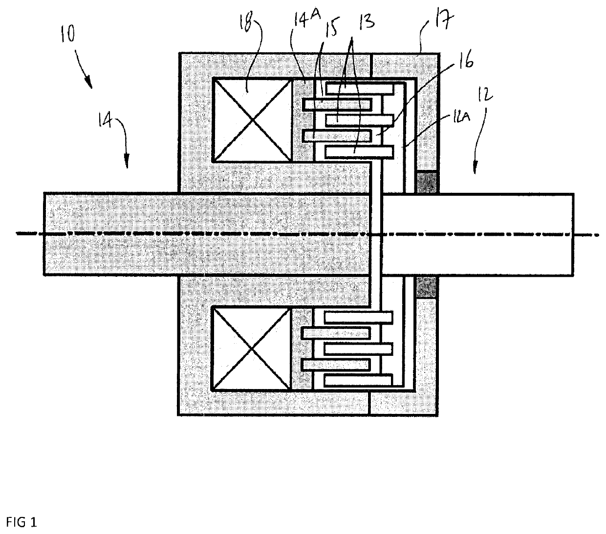
[0047]Referring to the drawings and more particularly to FIG. 1, there is illustrated a generic magnetorheological (MR) fluid clutch apparatus 10 configured to provide a mechanical output force based on a received input current. The MR fluid clutch apparatus 10 of FIG. 1 is a simplified representation of a MR fluid clutch apparatus that may be used in the systems described hereinafter. The MR fluid clutch apparatus that is used in the systems described hereinafter may have additional components and features, such as plates, redundant electromagnets, MR fluid expansion systems, etc.

[0048]The MR fluid clutch apparatus 10 has a driving member 12 with radial drums 13, this assembly also known as input rotor. The MR fluid clutch apparatus 10 also has a driven member 14 with drums 15 intertwined with the drums 13 to define one or more cylindrical chamber(s) filled with an MR fluid 16, the cylindrical chamber(s) being delimited by a casing 17 that is integral to the driven member 14. The a...


PUM


Abstract

A control system is provided for controlling movements of an end effector connected to a clutch output of at least one magnetorheological (MR) fluid clutch apparatus. A clutch driver is configured to drive the at least one MR fluid clutch apparatus between a controlled slippage mode, in which slippage between a clutch input and the clutch output of the MR fluid clutch apparatus varies, and a lock mode, in which said slippage between the clutch input and the clutch output is maintained below a given threshold, the clutch output transmitting movement to the end effector. A motor driver is configured to control a motor output of at least one motor, the motor output coupled to the clutch input. A mode selector module is configured to receive signals representative of at least one movement parameter of the end effector, the mode selector module selecting a mode between the controlled slippage mode and the lock mode of the clutch driver based on the signals, and switching the selected mode based on the signals. A movement controller controls the clutch driver and the motor driver to displace the end effector based on at least one of the selected mode and on commanded movements of the end effector for the end effector to achieve the commanded movements. A method for controlling movements of an end effector connected to the MR fluid clutch apparatus is also provided.

Description

CROSS-REFERENCE TO RELATED APPLICATION[0001]The present application claims priority on U.S. Patent Application No. 62 / 327,102, filed on Apr. 25, 2016 and incorporated herein by reference.FIELD OF THE APPLICATION[0002]The present application relates generally to magnetorheological (MR) fluid clutch apparatuses, and more particularly, to antagonist systems using such apparatuses.BACKGROUND OF THE ART[0003]State-of-the-art distributed power devices rely on hydraulics or electromagnetic actuation. Hydraulic actuation is reliable towards mechanical jam, but has fundamentally limited dynamic response and efficiency. Furthermore, implementation of hydraulic systems into commercial applications may be problematic as hydraulics are prone to leakage, leading to increased maintenance costs. Moreover, hydraulic actuation is hardware intensive.[0004]Electromagnetic actuation offers a clean alternative to hydraulic actuation. For high dynamic applications, the most common form of electromechanica...

Claims


Application Information

Patent Timeline
Patent Type & Authority Patents(United States)
IPC IPC(8): F16D37/00B25J19/00B25J9/14B25J19/06F16D7/02B25J9/10B25J9/12B25J13/08F16D27/10F16D48/06F16D37/02B25J9/16
CPCB25J9/1646B25J9/104F16D48/06B25J9/126B25J19/00B25J9/146B25J13/085F16D37/02B25J19/068F16D27/10F16D37/008B25J19/063B25J13/088F16D7/02F16D2037/001F16D2037/007F16D2027/008F16D2037/004F16D2500/10475F16D2500/30406F16D2500/3067
Inventor DENNINGER, MARCJULIO, GUIFREPLANTE, JEAN-SEBASTIENLAROSE, PASCAL
Owner EXONETIK INC
Why Eureka
Try Eureka