Pneumatic device

a technology of pneumatic devices and seats, applied in the field of pneumatic devices, can solve problems such as cumbersome manner, and achieve the effects of easy production, increased seat comfort for users or vehicle occupants, and high seat comfor

Active Publication Date: 2020-08-25
CONTI TEMIC MICROELECTRONIC GMBH
View PDF32 Cites 1 Cited by
  • Summary
  • Abstract
  • Description
  • Claims
  • Application Information

AI Technical Summary

Benefits of technology

[0006]According to a first aspect of the invention, a pneumatic device for the variation of a contour of a seat bearing surface of a vehicle seat is created. Said pneumatic device has a carrier foil composed of a first and a second foil ply which are arranged adjacent to one another. Here, the two foil plies are produced in particular as flexible foil plies composed of a plastic. Furthermore, the pneumatic device has a first bladder for varying the contour of the seat bearing surface, comprising a bladder chamber which can be filled with a pressure medium. Here, by filling and evacuating the bladder chamber, the volume of the bladder chamber can vary, such that, by means of this volume variation, a pressure and thus a variation can be imparted to the contour of the seat bearing surface. Finally, the pneumatic device has a first pressure medium line which is connected to the first bladder and which is formed or created between the first and the second foil ply by connection of the first and second foil plies along a first line-side connection seam in order to create a pressure medium connection to the first bladder chamber of the first bladder. Through this provision of the pressure medium line in the carrier foil itself, there is thus no longer a need for a separate pressure medium line, such that the production of the pressure medium line can be performed in a simple manner with minimized outlay in terms of method and apparatus.
[0018]In one refinement of the vehicle seat, the pneumatic device is arranged in the vehicle seat such that, in the region of the seat bearing surface (seat surface and / or seat surface), as lines for conducting pressure medium, only the pressure medium lines of the pneumatic device are provided. In this way, the seat comfort for a user or vehicle occupant is further increased, because no expanded and rigid components such as air hoses as pressure medium lines are used in the region in which the user makes contact with the seat bearing surface.

Problems solved by technology

In the case of such a construction, a large number of individual parts are thus required, which must be joined together in a cumbersome manner in complex manufacturing steps.

Method used


Image

  • Pneumatic device
  • Pneumatic device
  • Pneumatic device

Examples


Embodiment Construction

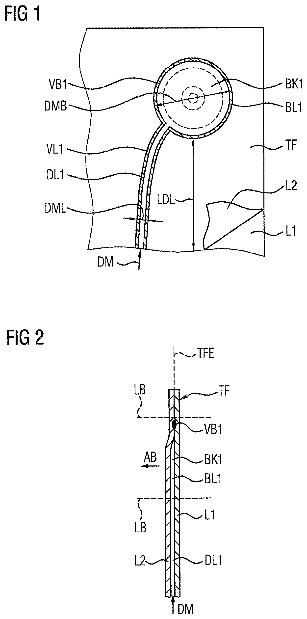
[0031]Reference is made firstly to FIG. 1, which shows a schematic plan view of a carrier foil TF. In conjunction with FIG. 2, which shows a corresponding schematic sectional illustration of the carrier foil TF from FIG. 1, it is now sought to discuss the construction of the carrier foil, with the structural elements implemented therein, for realizing a pneumatic device in particular for varying a contour of a seat bearing surface of a vehicle seat. Here, the carrier foil TF is composed of a first foil ply L1 and of a second foil ply L2 (and possibly further foil plies), which are arranged adjacent to one another. As an actuating element for influencing or varying the contour of a seat bearing surface of a vehicle seat, the carrier foil TF has a first bladder BL1. Said first bladder BL1 comprises in this case a bladder chamber BK1 which can be filled with pressure medium DM. Here, the first bladder is formed by connection of the first and second foil plies L1, L2 along a first bladd...


PUM


Abstract

A pneumatic device for varying a contour of a seat bearing surface includes a carrier foil TF composed of a first and a second foil ply which are arranged adjacent to one another. The pneumatic device has a first bladder for varying the contour of the seat bearing surface, including a bladder chamber which can be filled with pressure medium (DM). The pneumatic device furthermore has a first pressure medium line connected to the first bladder and which is formed by connection of the first and second foil plies along a line-side connection seam to create a pressure medium connection to the bladder chamber of the first bladder. One foil ply has, in the region of the first bladder, an opening in order to form a pressure medium channel to a further bladder, which can be filled with pressure medium and is connected to one of the foil plies.

Description

CROSS REFERENCE TO RELATED APPLICATIONS[0001]This application is the U.S. National Phase Application of PCT International Application No. PCT / EP2017 / 067339, filed Jul. 11, 2017, which claims priority to German Patent Application No. 10 2016 212 586.9, filed Jul. 11, 2016, the contents of such applications being incorporated by reference herein.FIELD OF THE INVENTION[0002]The present invention relates to a pneumatic device for the variation of a contour of a seat bearing surface of a vehicle seat. The present invention also relates to a vehicle seat having a device of said type. Finally, a method for producing a pneumatic device for varying the contour of a seat bearing surface of a vehicle seat is presented.BACKGROUND OF THE INVENTION[0003]In modern vehicle seats, bladders which can be filled with a pressure medium, in particular with a gaseous pressure medium such as compressed air, are situated as actuating elements in the region of the seat surface or backrest (together also refe...

Claims


Application Information

Patent Timeline
Patent Type & Authority Patents(United States)
IPC IPC(8): A47C4/54B60N2/90A61H9/00
CPCA61H9/0078B60N2/914B60N2/976A61H2201/0149
Inventor STEINBERGER, JOHANNTHIEL, WOLFGANG
Owner CONTI TEMIC MICROELECTRONIC GMBH
Why Eureka
Try Eureka