Method for switching an operating state of an electric machine and device for switching an operating state of an electric machine

a technology of operating state and electric machine, which is applied in the direction of electrodynamic brake system, ac motor stopper, transportation and packaging, etc., can solve the problems of damage or destruction of the components of the inverter or of the components connected to the inputs and outputs, and high overvoltage and/or overcurrent occurren

Active Publication Date: 2019-11-19
ROBERT BOSCH GMBH
View PDF14 Cites 0 Cited by
  • Summary
  • Abstract
  • Description
  • Claims
  • Application Information

AI Technical Summary

Benefits of technology

[0017]A possibility for switching from the freewheeling operating state to the short-circuit operating state of an electric machine is thus made available which does not cause destruction or damage on the components.
[0029]Since the second switching element can be closed within a range comprising the switching points in time of the third and first switching elements, it is appropriate to close the second switching element simultaneously with one of the other switching elements; in particular, two switching elements can thus be driven by means of one drive signal. This advantageously simplifies the driving and minimizes the outlay on resources in the control.
[0032]This advantageously ensures that the power factor is taken into account upon the short-circuiting of the individual phases and, therefore, no overvoltages or overcurrants arise or these are minimized.

Problems solved by technology

The closing of the power switches of the inverter in order to change from the freewheeling operating state to the short-circuit operating state is accompanied by the occurrence of high overvoltages and / or overcurrents between the inverter and the electric machine in the individual phases.
These can lead to damage or destruction of the components of the inverter or of the components connected to the inputs and outputs.

Method used


Image

  • Method for switching an operating state of an electric machine and device for switching an operating state of an electric machine
  • Method for switching an operating state of an electric machine and device for switching an operating state of an electric machine
  • Method for switching an operating state of an electric machine and device for switching an operating state of an electric machine

Examples


Embodiment Construction

[0040]In the figures, identical or identically acting functions or functional features and components, unless explained otherwise, are provided in each case with the same reference signs. It goes without saying that components and elements in the drawings are not necessarily reproduced in a manner true to scale, for reasons of clarity.

[0041]Further possible configurations and developments and implications of the invention also encompass combinations—not explicitly mentioned—of above—or below—described features of the invention.

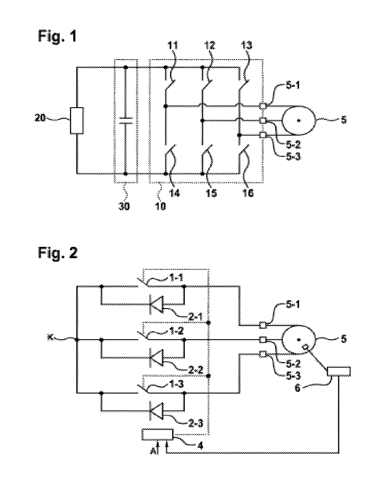
[0042]FIG. 1 shows a schematic illustration of a power converter arrangement for operating an electric machine 5. The power converter arrangement comprises an energy source 20, such as, for example, a traction battery of an electrically driven motor vehicle, a DC link circuit 30, which comprises in particular a link circuit capacitor, and a power converter 10. The electric machine 5 may be for example a synchronous motor or a synchronous machine.

[0043]In this ...


PUM


Abstract

The invention relates to a method and to a device for changing from the idle operating state of an electric motor (5) having three phase terminals (5-1, 5-2, 5-3) to a short-circuit operating state. Thereby significant voltage rises are avoided. For this purpose, after receiving (120) a request for changing of the operating state of the electric motor (5) to the short-circuit operating state, three switching elements (1-1, 1-2, 1-3) are closed. Thereby the switching elements (1-1, 1-2, 1-3) are at least partially closed successively and the times of closing the individual switching elements are predetermined as a function of control parameters of the electric motor.

Description

BACKGROUND OF THE INVENTION[0001]The present invention relates to a method and a device for switching from the freewheeling operating state of an electric machine to the short-circuit operating state.[0002]Furthermore, the invention relates to a power converter and also an electrically driven motor vehicle comprising a device for switching from the freewheeling operating state of an electric machine to the short-circuit operating state.[0003]Electric machines, such as permanently excited synchronous machines, for example, are used in numerous technical fields. By way of example, such permanently excited synchronous machines are used in motor vehicles. For safety reasons it is necessary here to take precautions for a safe operating state in the case of a fault. One possibility for a safe operating state is the so-called active short circuit, for example. In this case, the phase terminals of the electric machine are short-circuited simultaneously by means of suitable switching element...

Claims


Application Information

Patent Timeline
Patent Type & Authority Patents(United States)
IPC IPC(8): B60L7/00H02P3/22
CPCB60L7/003H02P3/22H02P29/0241Y02T10/64
Inventor GROSSMANN, EKARDABELE, MARCUSHEIDRICH, TORSTEN
Owner ROBERT BOSCH GMBH
Why Eureka
Try Eureka