Projector system

a projector and projection device technology, applied in the field of projector systems, can solve the problems of difficult detection in the peripheral region of the detection range, false detection or unsuccessful detection, and achieve the effect of reliable detection of the position of the pointing elemen

Active Publication Date: 2020-08-25
SEIKO EPSON CORP
View PDF37 Cites 0 Cited by
  • Summary
  • Abstract
  • Description
  • Claims
  • Application Information

AI Technical Summary

Benefits of technology

[0004]An aspect of the invention is to provide a projector system capable of detecting a pointing element over a wide range and further capable of reliably detecting the position of the pointing element even when the attitude of the pointing element changes.
[0006]In the projector system described above, the imager, which operates based on the stereographic projection scheme, can have an increased angle of view, can therefore capture not only an image of the projection region where the obliquely projected image light is projected but an image of the stereographic region containing the projection region, and can further reliably grasp the pointing element present in the stereographic region. In particular, employing the stereographic projection scheme can avoid a situation in which a change in the angle of the pointing element, which is a subject, distorts the pointing element and reduce the size thereof in an image while suppressing difficulty in optical design of the imager, whereby the position of the pointing element can be reliably detected.

Problems solved by technology

When the detection range widens, however, it is difficult to perform detection in a peripheral region of the detection range.
In this case, false detection or unsuccessful detection is quite likely to occur.

Method used


Image

  • Projector system
  • Projector system
  • Projector system

Examples


first embodiment

[0036]A projector system according to a first embodiment of the invention will be described below with reference to the drawings.

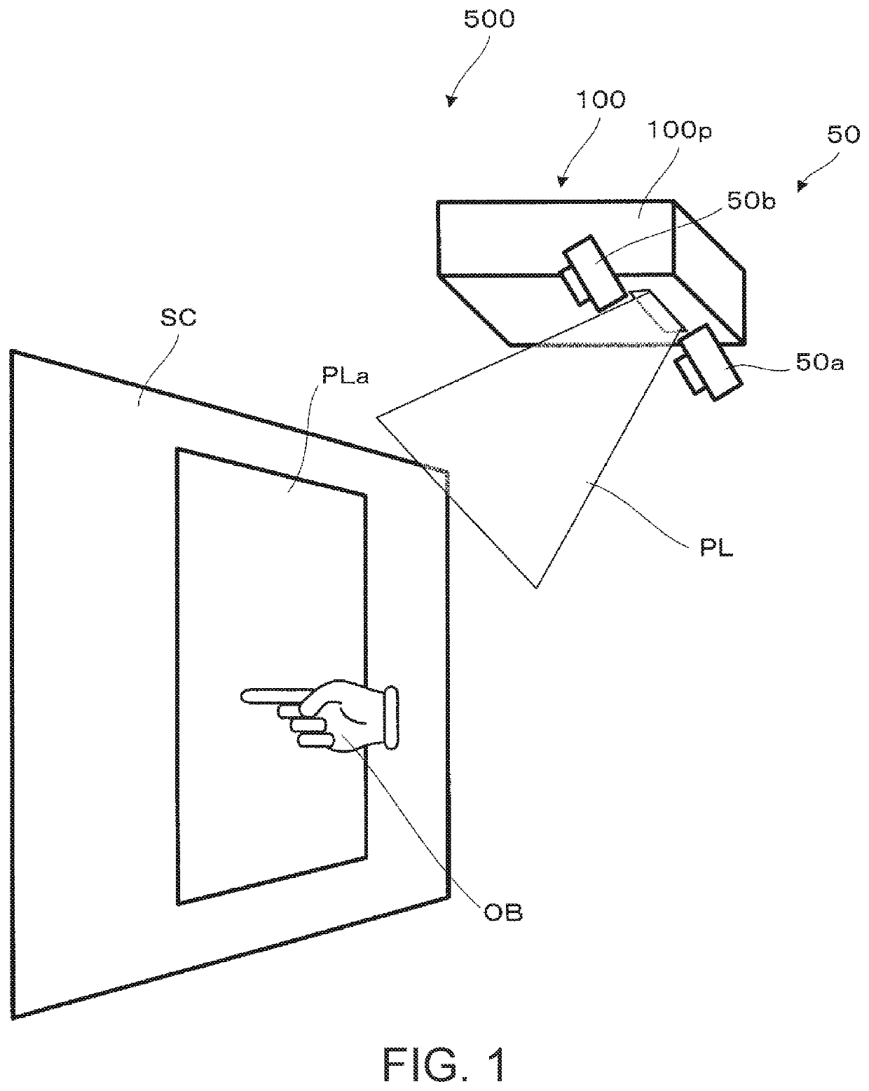
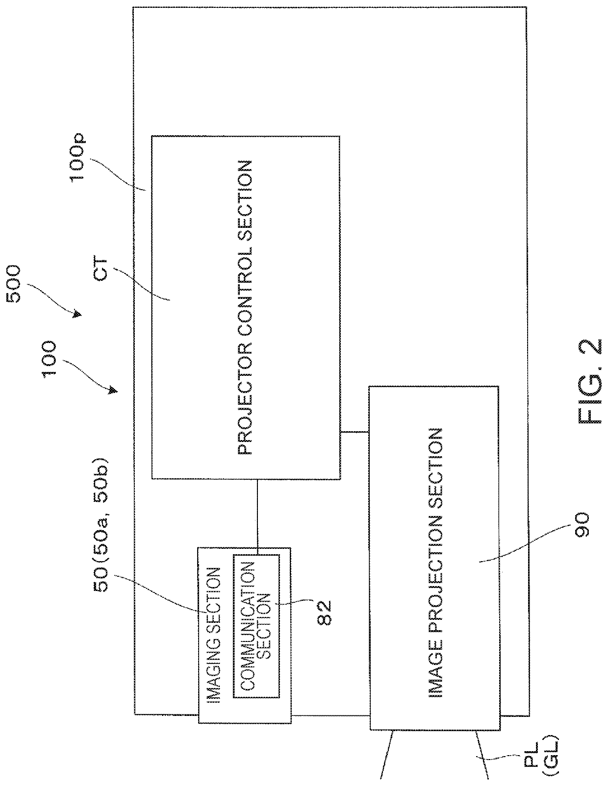
[0037]A projector system 500 shown FIG. 1 and other figures is formed of a projector 100, which (obliquely) projects projection light PL, which is image light, for image projection. A radiated region PLa, onto which the projection light PL is radiated, is formed, for example, on a screen SC. The radiated region PLa corresponds to the region where the projection light (image light) PL from the projector 100 is projected. Although not shown, the projector system 500 is formed not only of the projector 100 but of a PC or any other apparatus connected to the projector system 500 and allows image operation in an interactive situation in which the PC carries out a variety of processes as required to accept writing operation performed on a display screen in the radiated region PLa. Among the components of the projector system 500, the projector 100 is a short-foc...

second embodiment

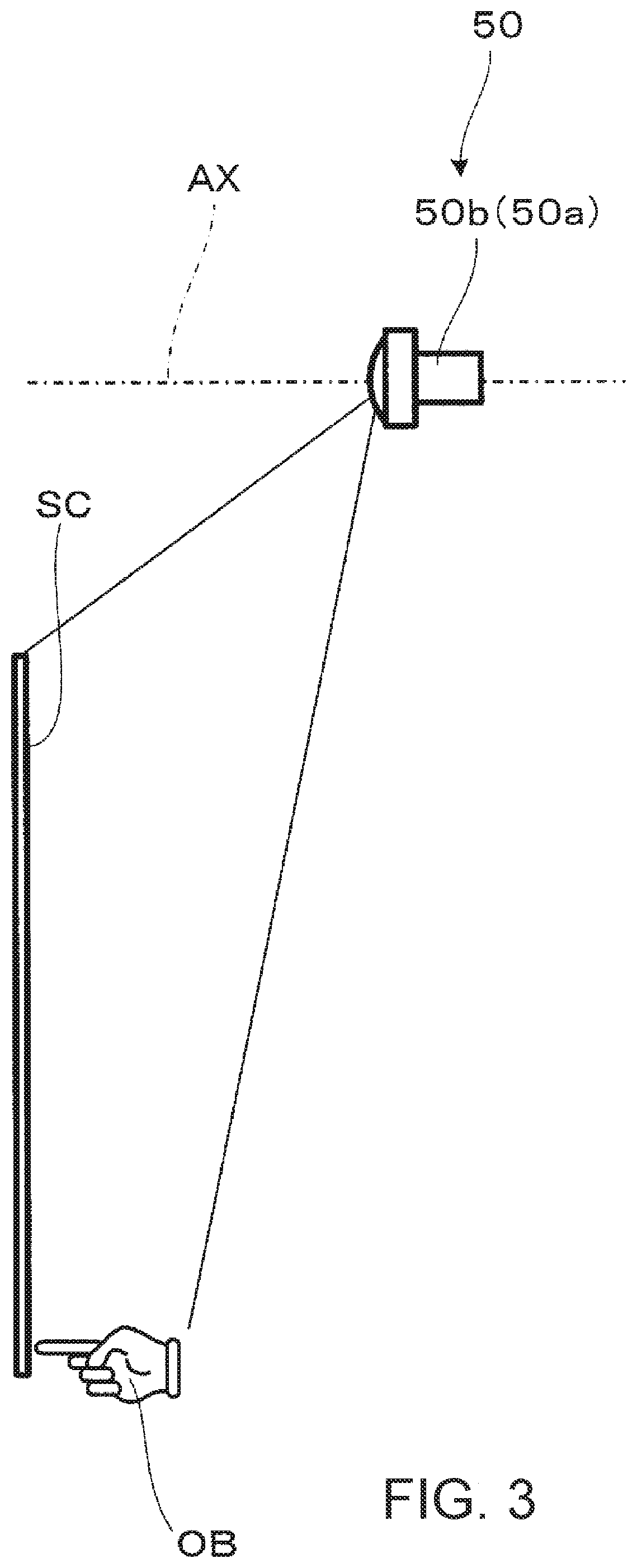
[0063]A second embodiment, which is a variation of the first embodiment, will be described below with reference to FIG. 15. A projector sys tem according to the present embodiment has the same configuration as that in the first embodiment except that the attitude (tilt angle) of the imager 50 is changed, and illustration and description of the entire projector system will be omitted. Further, it is assumed that a specific configuration example (specific specifications) is the same as that shown in the first embodiment. The present embodiment, however, in which the tilt angle is changed, differs from the first embodiment in that the focal length f changes with an increase or decrease in the tilt angle (focal length f is unchanged in first embodiment because tilt angle is 0°).

[0064]FIG. 15 describes the attitude and the imaging range of an imager 150 in the projector system according to the present embodiment and corresponds to FIG. 3. It is assumed that the imager 150 is formed of ca...


PUM


Abstract

A projector system includes a projector main body that obliquely projects image light and an imager that operates based on a stereographic projection scheme and captures an image of a stereographic region containing a projection region where the image light from the projector main body is projected to detect a pointing element present in the stereographic region.

Description

BACKGROUND1. Technical Field[0001]The present invention relates to a projector system for achieving what is called an interactive projector capable of wiring operation by detecting a pointing element, such as a finger, present on a projection screen and reflecting the detected pointing element in the content of a projected image.2. Related Art[0002]JP-A-2015-159524 discloses a projector that achieves the interactive function by providing a light output apparatus that is provided separately from a projection mechanism of the projector and outputs infrared light in such a way that a layer of the infrared light is formed substantially across a projection screen (screen) and detecting the infrared light outputted from the light output apparatus and reflected off the tip of a pointing element (fingertip, for example) to detect pointing operation performed via the pointing element. In the configuration described above, however, an apparatus that radiates laser light is necessary, and prec...

Claims


Application Information

Patent Timeline
Patent Type & Authority Patents(United States)
IPC IPC(8): G06F3/042H04N9/31H04N13/239G06T7/70G06V10/145
CPCH04N9/31H04N13/239G06T7/70G06F3/042G06T2207/10012G06T2207/30196G03B21/00G03B21/14G06F3/0346G06F3/0425H04N9/3194H04N9/3179G06V40/113G06V10/145
Inventor OTANI, MAKOTO
Owner SEIKO EPSON CORP
Why Eureka
Try Eureka