System for applying maximum driving efficiency point of load

a technology of driving efficiency and load, applied in the direction of dynamo-electric converter control, dynamo-electric brake control, dynamo-electric gear control, etc., can solve the problems of increased energy waste and unnecessary energy consumption, and achieve the effect of reducing energy to the maximum, reducing the amount of electric power used, and maximizing the operating efficiency poin

Active Publication Date: 2020-08-25
KOREA DIGITAL CONTROL
View PDF10 Cites 0 Cited by
  • Summary
  • Abstract
  • Description
  • Claims
  • Application Information

AI Technical Summary

Benefits of technology

[0051]As described above, according to the load maximum efficiency point applying system of the present invention, by controlling both the speed and the voltage of the motor, it is possible to select the lowest frequency within the allowable range, and at the same time, by controlling the voltage to the maximum, the power can be reduced to the maximum, thereby making it possible to minimize the amount of electric power used and to reduce the energy to the maximum. That is, in the present invention, the maximum operating efficiency point of the load of the motor powered machine can be applied.

Problems solved by technology

In this way, when the power supply voltage is directly connected to the motor driving the load of the quadratic torque type, energy waste is increased.
Therefore, it has been causing unnecessary energy consumption under partial load conditions.

Method used


Image

  • System for applying maximum driving efficiency point of load
  • System for applying maximum driving efficiency point of load
  • System for applying maximum driving efficiency point of load

Examples


first embodiment

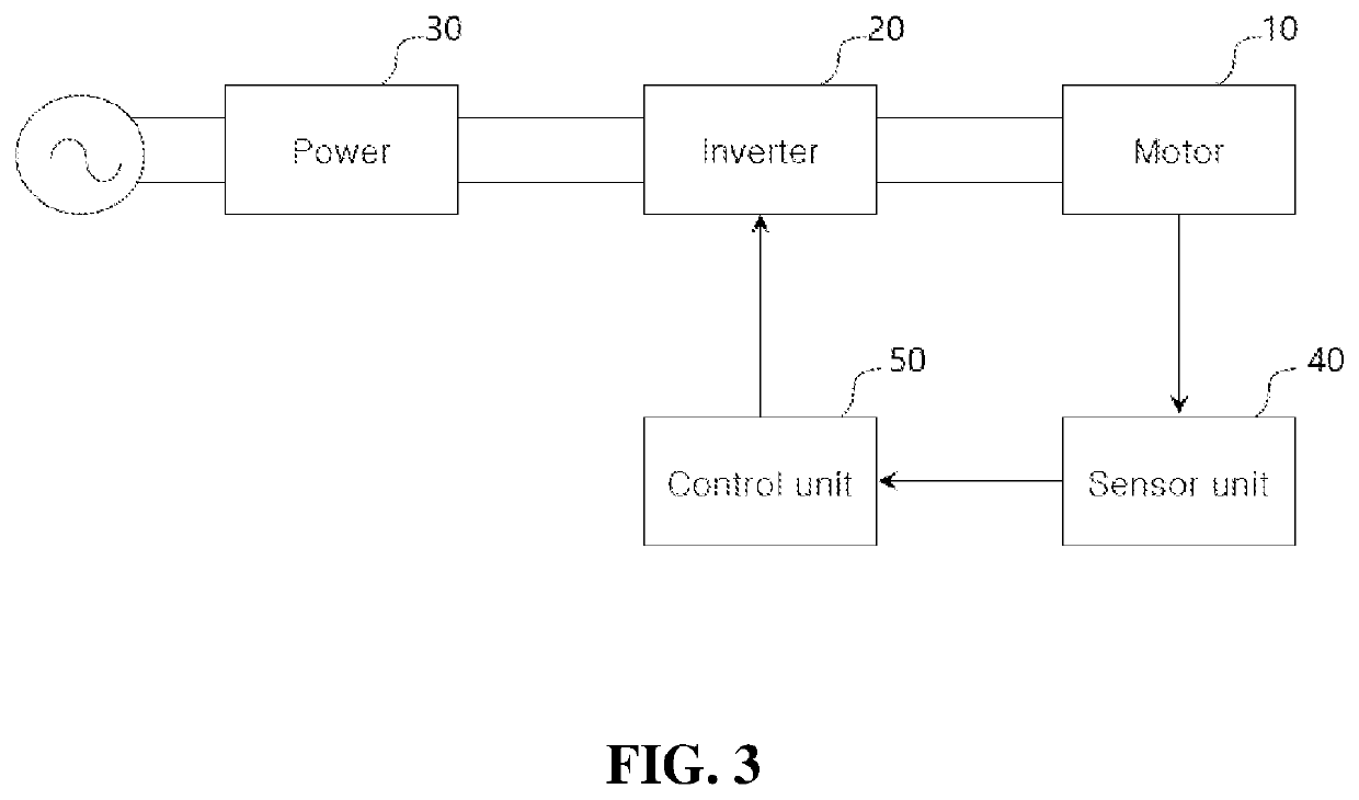
[0061]First, the configuration of the load maximum operating efficiency point application system for a load according to the present invention will be described with reference to FIG. 3.

[0062]As shown in FIG. 3, a system for applying maximum driving efficiency point of load according to the present invention, comprising, the motor 10 for driving the load, an inverter 20 for controlling the speed and the voltage of the motor 10, an a power supply unit 30 for receiving an AC commercial power supply and supplying power to the inverter 20, a sensor unit 40 for measuring the maintaining current and the maintaining current of the motor 10, and a control unit 50 for controlling the voltage and frequency (or speed) of the inverter 20 so as to have the maximum efficiency in consideration of the flow rate to be supplied and the maximum supply time.

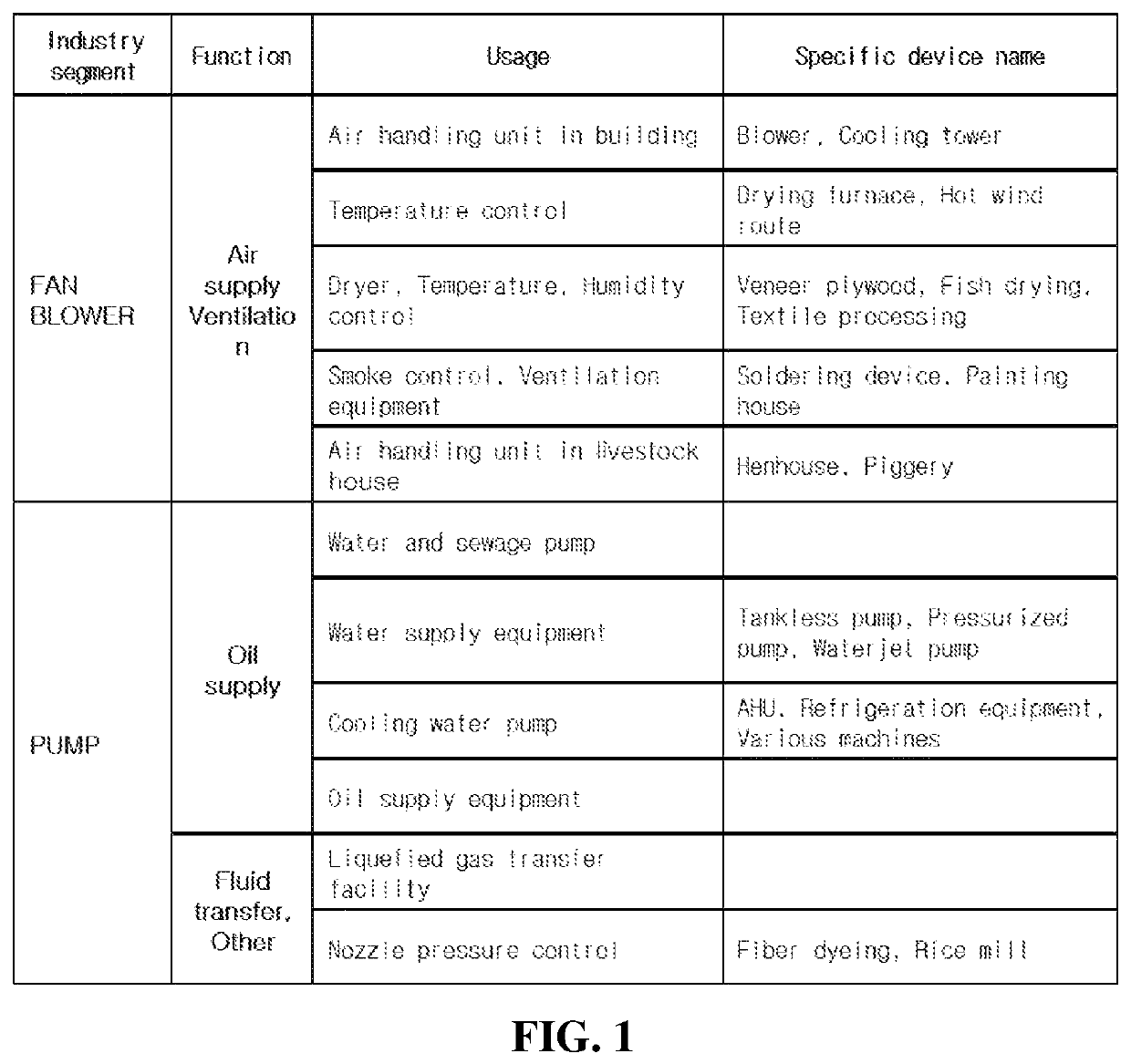
[0063]The motor 10 is an induction motor that drives a load. For example, the load refers to a load such as an air conditioning fan or a pump that ...

second embodiment

[0115]Next, a configuration and a control method of a maximum operating efficiency point application system for a load according to the present invention will be described with reference to FIG. 6

[0116]The second embodiment of the present invention controls by the proportional power factor of the input current and the torque current in order to control the inverter instead of using the ROC of formula 5. Only the parts different from the first embodiment will be described below. For the unexplained part, the explanation of the first embodiment described above may be referenced.

[0117]First, in the second embodiment of the present invention, the sensor unit 40 is composed of current sensors for measuring the input current (I) and the torque current (Iq) in the motor 10.

[0118]Next, a method of controlling the inverter of the motor according to the second embodiment of the present invention will be described with reference to FIG. 6.

[0119]First, the speed N of the inverter 20 is determin...

third embodiment

[0127]Next, a configuration and a control method of a maximum operating efficiency point application system for a load according to the present invention will be described with reference to FIG. 7.

[0128]In a third embodiment of the present invention, the change amount of the total current after the voltage drop is additionally checked in the first embodiment, and the previous voltage is set as the final voltage when the total current increases. Only the parts different from the first embodiment will be described below. For the unexplained part, the explanation of the first embodiment described above may be referenced. As shown in FIG. 7, the speed N of the inverter 20 is first determined (S210), and an initial voltage corresponding to the set speed is set (S220). Next, the magnetic flux maintaining current (Id) and the torque current (Iq) of the motor 10 are measured (S230), and the rate of change (ROC) of the proportional amount of the torque current (Iq) to the magnetic flux maint...


PUM


Abstract

A system for applying maximum driving efficiency point of load includes: a motor for driving a load; an inverter for controlling the speed and the voltage of the motor; a sensor unit for measuring the magnetic flux maintaining current and the torque current of the motor; and a control unit determining the speed of the inverter and using the proportional value of the magnetic flux maintaining current and the torque current measured within a range in which the total current does not increase when the motor is driven at the determined speed. The motor inverter control system can control both motor speed and voltage to select the lowest frequency within the permissible range and at the same time control the voltage at the water head to maximize power, thereby reducing power consumption to a minimum.

Description

TECHNICAL FIELD[0001]The present invention relates to a system for controlling a motor driving a load such as a fan, pump, blower, etc., and controlling the speed and voltage of the motor at the same time to apply the maximum efficiency point of the load.BACKGROUND ART[0002]Generally, in order to drive the air-conditioning fan or the pump circulating the water, the torque of the driving motor has to be increased in proportion to the square of the speed. In this way, when the power supply voltage is directly connected to the motor driving the load of the quadratic torque type, energy waste is increased. In other words, if a power frequency of 60 Hz is used as a reference of the rotation speed and an induction motor having 4 poles is taken as an example, the reference speed becomes 1800 rpm, and the speed is operated regardless of the load condition. Therefore, it has been causing unnecessary energy consumption under partial load conditions. This problem can be solved by applying an i...

Claims


Application Information

Patent Timeline
Patent Type & Authority Patents(United States)
IPC IPC(8): H02P27/08H02P21/22H02P21/00H02P27/06
CPCH02P27/08H02P27/06H02P21/00H02P21/22H02P23/26H02P27/047H02P21/0003
Inventor LEE, YONG HAELEE, JUNG HOON
Owner KOREA DIGITAL CONTROL
Why Eureka
Try Eureka