Simulation device, simulation method, and recording medium

a technology of simulation device and simulation method, applied in the direction of electrical programme control, program control, instruments, etc., can solve the problems of inability to achieve the maximum capacity of the equipment, a lot of labor to achieve the optimal collaboration of the prepared equipment, and a long time to construct an appropriate production line, so as to achieve the effect of accurately simulating an amount of electric power consumption

Active Publication Date: 2014-11-06
ORMON CORP
View PDF6 Cites 5 Cited by
  • Summary
  • Abstract
  • Description
  • Claims
  • Application Information

AI Technical Summary

Benefits of technology

[0015]Due to the increasing awareness of a CO2 reduction in recent years, there is an increasing need for design which not only shortens a production takt and minimizes a production cost, but also minimizes an amount of electric power consumption. The techniques described in Patent Literatures 1 through 4, however, do not consider electric power consumption.
[0018]One or more embodiments of the present invention provides a simulation apparatus, a simulation method, a program, and a recording medium that can accurately simulate an amount of electric power consumption of a piece of equipment and output the amount of electric power consumption thus simulated.
[0020]According to the simulation apparatus of one or more embodiments of the present invention, it is possible to produce an effect of highly accurately simulating an amount of electric power consumption of a piece of equipment and outputting the amount of electric power consumption thus simulated.

Problems solved by technology

However, in a case where a production line is constructed by the method shown in FIG. 22, it takes a lot of labor to achieve optimum collaboration of the pieces of equipment prepared based on the design of the production steps.
Moreover, it takes a long time to construct an appropriate production line, for example, because of occurrence of the necessity of redesigning the production steps back at the design process.
Furthermore, failure to achieve maximum capacities of the pieces of equipment or failure to accomplish the designed production capacity are likely to occur because of occurrence of a standby time, an idling time, or the like necessitated due to collaboration with the other pieces of equipment.
The techniques described in Patent Literatures 1 through 4, however, do not consider electric power consumption.
However, the amount of electric power consumption thus calculated does not take into consideration suspension and standby states of each piece of equipment, and is therefore far larger than an actual amount of electric power consumption of the production line.
Therefore, an improvement in accuracy of a simulation result of an amount of electric power consumption cannot be expected.

Method used


Image

  • Simulation device, simulation method, and recording medium
  • Simulation device, simulation method, and recording medium
  • Simulation device, simulation method, and recording medium

Examples


Embodiment Construction

[0044]A simulation apparatus for simulating a production line according to embodiments of the present invention is described below with reference to the drawings. In embodiments of the invention, numerous specific details are set forth in order to provide a more thorough understanding of the invention. However, it will be apparent to one of ordinary skill in the art that the invention may be practiced without these specific details. In other instances, well-known features have not been described in detail to avoid obscuring the invention.

[0045]

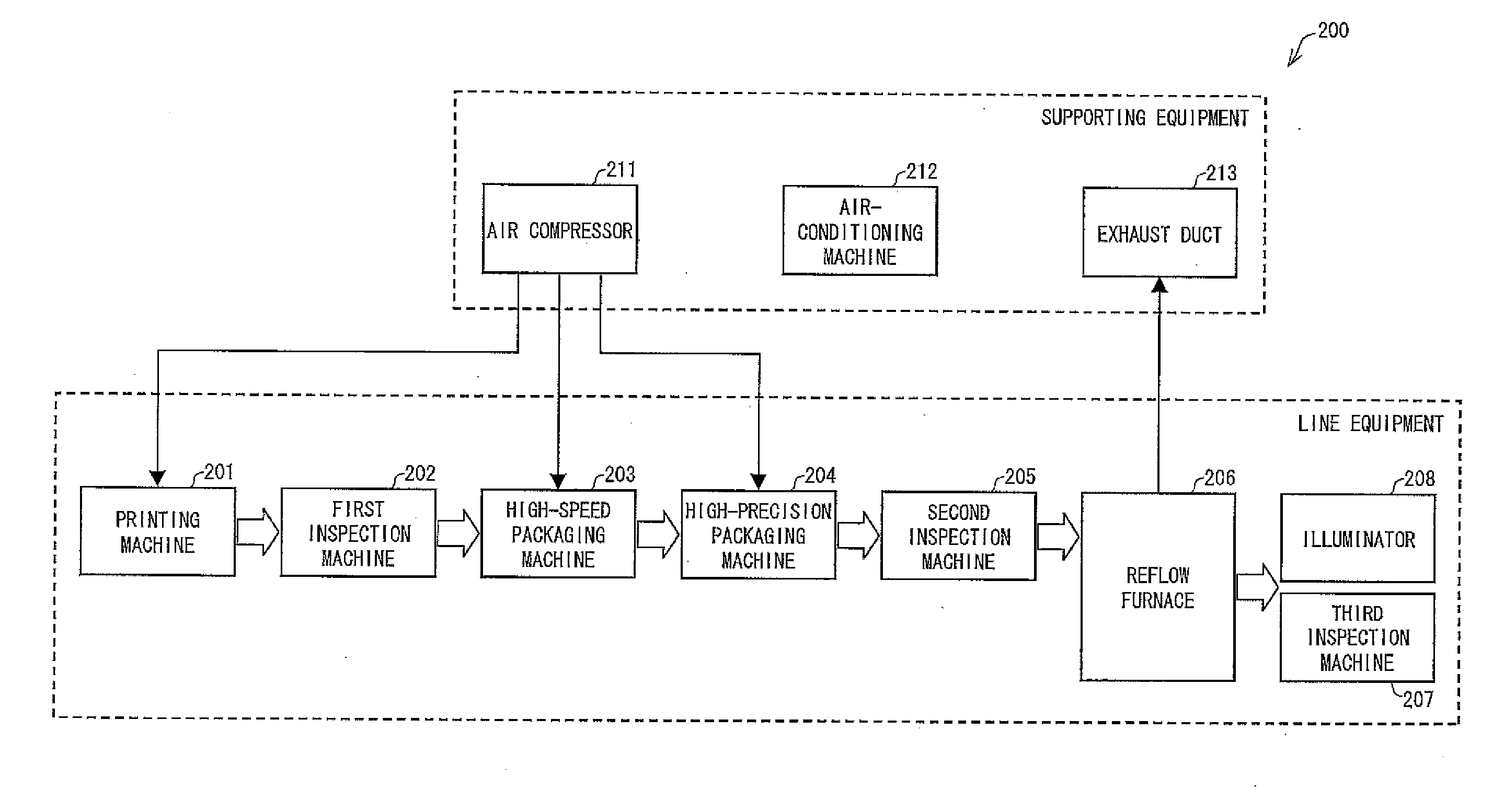
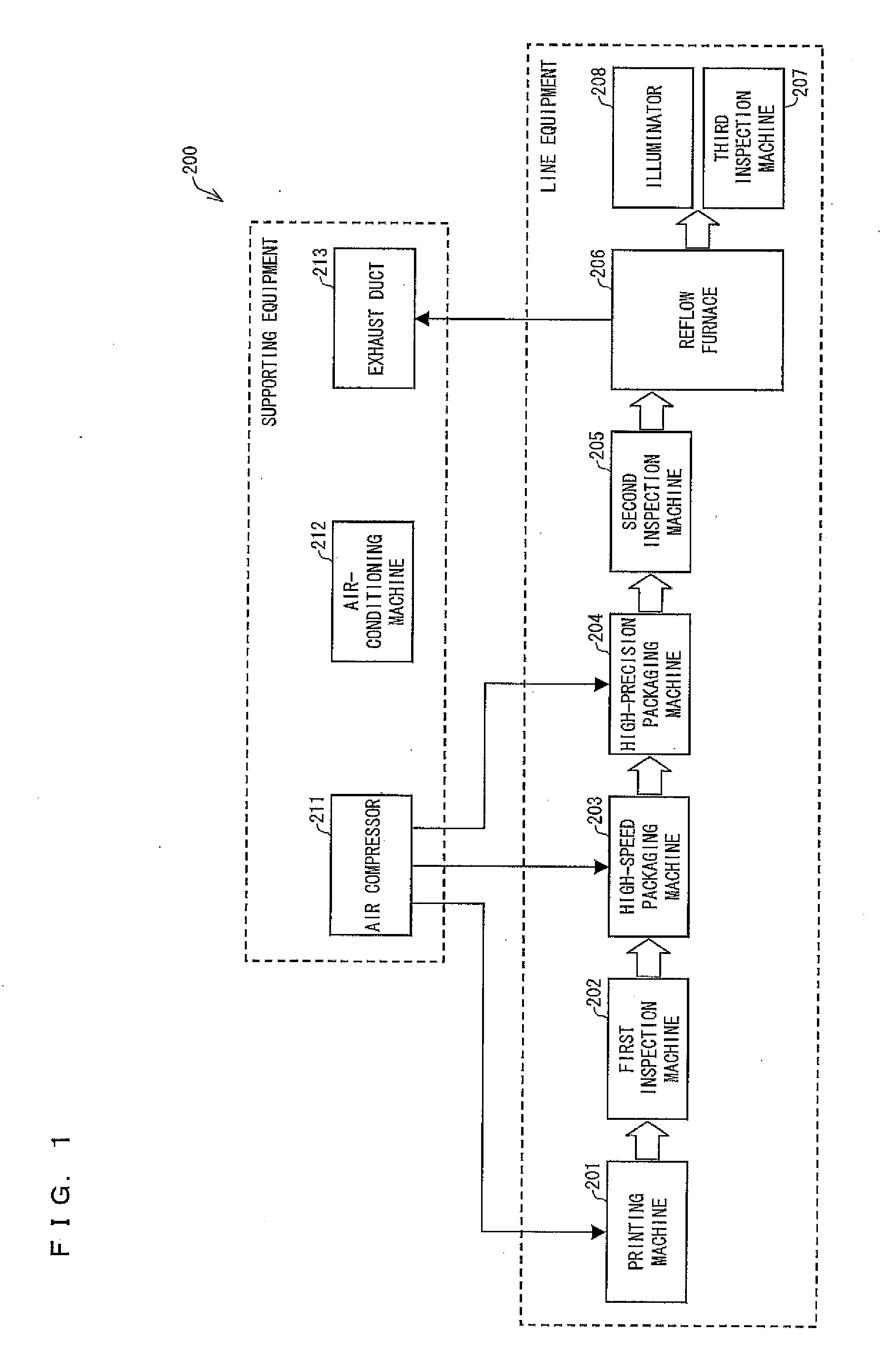
[0046]FIG. 1 shows an example of a virtual model of a production line as configured by a simulation apparatus according to one or more embodiments of the present invention. As shown in FIG. 1, the virtual model 200 is a model of a production line for fabricating electronic component packaged boards by packaging electronic components onto printed circuit boards.

[0047]The virtual model 200 includes: a printing machine 201 for printing soldering ...


PUM


Abstract

A simulation apparatus has a type setting section that sets a type of mode of electric power consumption of equipment, and an output section that simulates an amount of the electric power consumption of the equipment in accordance with the type set by the type setting section and outputting the amount of electric power consumption thus simulated.

Description

BACKGROUND[0001]1. Technical Field[0002]The present invention relates to a simulation apparatus that simulates an amount of electric power consumption of a piece of equipment and outputs the amount of electric power consumption thus simulated.[0003]2. Related Art[0004]Conventionally, a production line is known, which successively processes or assembles electronic components, mechanical components, or the like with the use of a plurality of pieces of equipment. Such a production line is constructed by a method such as the one shown in FIG. 22. First, production steps are designed based on information such as a material, a shape, and components of a product (S100). Next, a production line is determined by introducing and disposing, in accordance with a production capacity, resources (e.g. pieces of equipment, machine tools, carrying means, and personnel) for achieving the production steps (S101). Then, the production capacity is evaluated while actually producing a product on the prod...

Claims


Application Information

Patent Timeline
Patent Type & Authority Applications(United States)
IPC IPC(8): G06F17/50
CPCG06F17/5009G05B17/02G06Q50/06G05B2219/25387G05B17/00G05B19/418G06F30/20
Inventor KAWAI, WAKAHIRO
Owner ORMON CORP
Why Eureka
Try Eureka