Trans-horizon wireless communication system using the tropospheric evaporation duct

a wireless communication and tropospheric evaporation technology, applied in the field of wireless communication methods and systems, can solve the problems of insufficient infrastructure, inability to extend trans-horizon wireless communication beyond line-of-sight (los), and inability to meet the needs of trans-horizon wireless communication, etc., to achieve high availability and/or capacity.

Active Publication Date: 2020-08-25
GASOLINEIAM NASIONAL BERHAD
View PDF1 Cites 1 Cited by
  • Summary
  • Abstract
  • Description
  • Claims
  • Application Information

AI Technical Summary

Benefits of technology

[0007]In accordance with a first aspect of the present invention, a system for a trans-horizon wireless communication link using an evaporation duct over a sea is provided. The system includes (n×n) MIMO based transceiver microwave radio circuitry, two or more antennas and adaptive modulation and demodulation circuits at both ends of the wireless communication link. The two or more antennas are vertically and / or horizontally arranged antennas and are placed within twenty-five meters above a mean sea level of the sea. The adaptive modulation and demodulation circuits are coupled at each end of the wireless communication link to the transceiver microwave radio circuitry and the two or more antennas and vary pathloss conditions to achieve high availability and / or capacity for beyond line-of-sight distances of the wireless communication link within the evaporation duct.
[0008]In accordance with a further aspect, the (n×n) MIMO system includes a (n×n) MIMO system, where n is greater than or equal to two and selected for the (n×n) MIMO system to maximize diversity gain.
[0009]In accordance with yet a further aspect, the transceiving circuitry adaptively modulates information onto transmission signals in response to varying pathloss of the transmission signals to maximize the availability and / or throughput rate of the wireless communication link.
[0012]In accordance with a further aspect, the vertical and / or horizontal separation of the two or more vertically and / or horizontally antennas at the first over sea transceiving location and the second over sea transceiving location are selected to maximize received signals to improve availability and / or capacity in both slow and fast fading environment of the evaporation duct.
[0013]In accordance with another aspect, the first one of the adaptive modulation and demodulation circuits and the second one of the adaptive modulation and demodulation circuits work together with the first and second sets of the two or more antennas to improve system performance of the trans-horizon wireless communication link to handle more pathloss than can be catered by gains from the first and second sets of the two or more antennas.
[0014]And, in accordance with yet another aspect of the present invention, the first and second ones of the adaptive modulation and demodulation circuits improve system performance by maximizing capacity for a given availability requirement in slow and fast fading conditions of the evaporation duct environment.

Problems solved by technology

Wireless communication beyond line-of-sight (LOS) is generally not possible over either land or sea.
Over the sea or the ocean or any large bodies of water (such as large lakes), however, such infrastructure is nonexistent due to difficulty of installations in the water.
While line-of-sight based wireless communication using microwave radio can be established over the ocean, prohibitively high cost infrastructure is required in the middle of the ocean for extending trans-horizon wireless communication.
Satellite communication can facilitate such communication, however, over the sea, there are serious limitations such as high cost, data rate and traffic limitations and availability.
However, such systems have been unable to show establishment of neither a reliable communication link nor a high data rate throughput which can match a satellite or a LOS microwave-based broadband link.

Method used


Image

  • Trans-horizon wireless communication system using the tropospheric evaporation duct
  • Trans-horizon wireless communication system using the tropospheric evaporation duct
  • Trans-horizon wireless communication system using the tropospheric evaporation duct

Examples


Embodiment Construction

[0028]The following detailed description is merely exemplary in nature and is not intended to limit the invention or the application and uses of the invention. Furthermore, there is no intention to be bound by any theory presented in the preceding background of the invention or the following detailed description. It is the intent of the present embodiment to present a reliable wireless communication system for trans-horizon communication over the sea using the tropospheric evaporation duct.

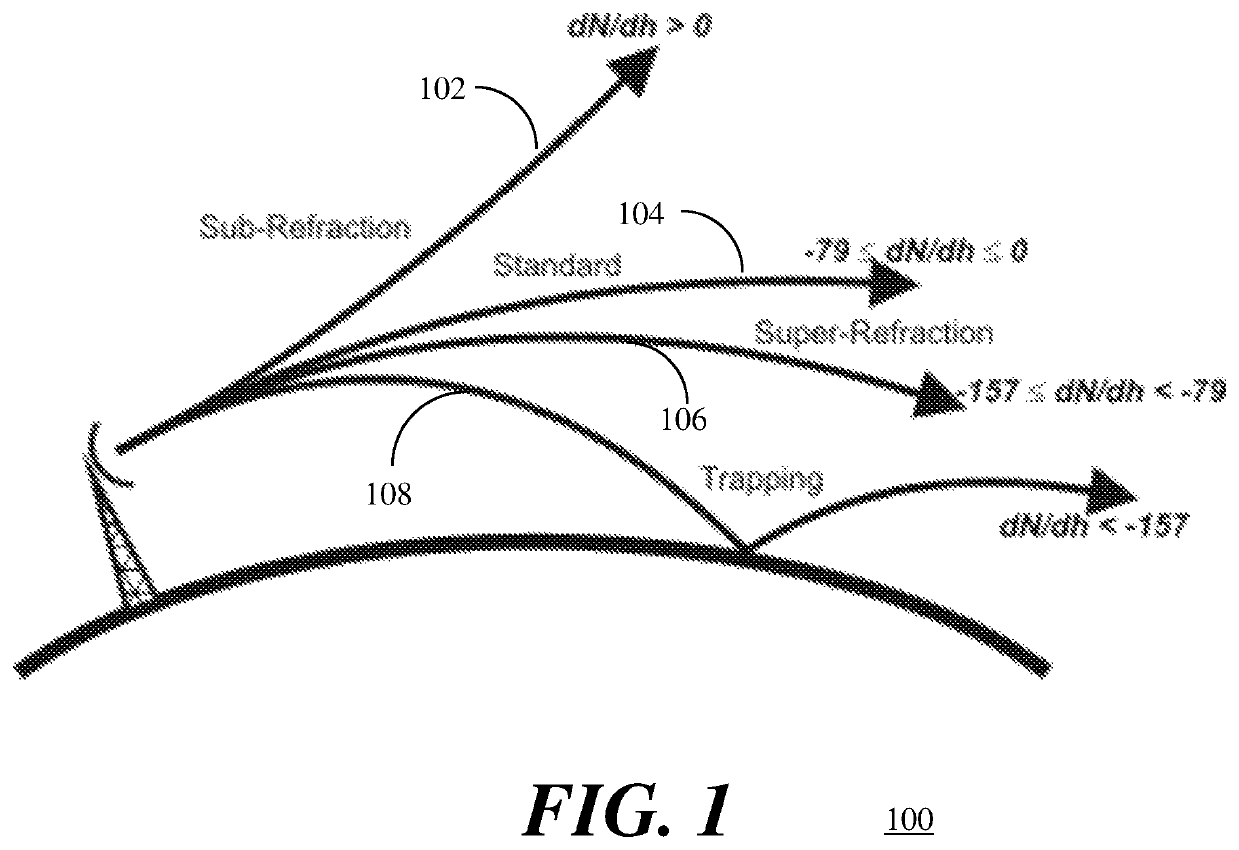
[0029]Referring to FIG. 1, an illustration 100 depicts four refractive conditions which depend upon refractive gradients. In standard conditions 102, the gradient of refractivity varies from 0 to −79 N-units per km. When the refractivity gradient varies from −79 to −157 N-units per km, a super-refraction condition 104 occurs in the troposphere and the ray will refract downwards at a rate greater than standard but less than the curvature of earth. If the refractivity gradient is greater than 0 N-un...


PUM


Abstract

A system for trans-horizon tropospheric-based wireless communication is provided. The system provides high availability and capacity as compared to a line-of-sight (LOS) standard microwave radio link while using very low height antenna towers. The system includes n×n MIMO transceiver circuitry and two or more antennas and adaptive modulation and demodulation in response to slow varying pathloss. Each of the two or more antennas is located at a vertical height above an average sea mean level within the evaporation duct. Availability percentage for different pathloss ranges along with adaptive modulation contributes to the overall availability according to the varying evaporation duct height.

Description

CROSS-REFERENCE TO RELATED APPLICATION(S)[0001]This application is a U.S. National Phase Patent Application and claims priority to and the benefit of International Application Number PCT / MY2017 / 050064, filed on Oct. 26, 2017, which claims priority of Malaysian Patent Application Number PI 2016001909, filed on Oct. 26, 2016, the entire contents of all of which are incorporated herein by reference.TECHNICAL FIELD[0002]The present invention generally relates to methods and systems for wireless communication, and more particularly relates to methods and systems for trans-horizon wireless communication using the tropospheric evaporation duct over the sea or the ocean.BACKGROUND OF THE DISCLOSURE[0003]Wireless communication requires a transmitter, a receiver and a communication channel. Wireless communication beyond line-of-sight (LOS) is generally not possible over either land or sea. Over land, the communication link can be extended by repeaters and landline connections to increase the ...

Claims


Application Information

Patent Timeline
Patent Type & Authority Patents(United States)
IPC IPC(8): H04B7/02H04B1/7115H04B7/024H04B7/10H04B7/0413
CPCH04B7/024H04B7/10H04B7/0413H04B7/028H04B1/7115
Inventor JEOTI, VARUNIQBAL, ASIFZAIDI, KHURRAM SHABIHDRIEBERG, MICHEALWONG, PENG WENOSMAN, M SHARIF
Owner GASOLINEIAM NASIONAL BERHAD
Why Eureka
Try Eureka