
Fence brace system adapted for use with cylindrical fence posts

a brace system and cylindrical technology, applied in the field of fence brace system, can solve the problems of damage to fences and fence structures, wind damage to fences all around the world, and special wind damage to fences made of wood, etc., and achieve the effect of easy adaptation, low cost and mass production

Active Publication Date: 2020-09-01
CRANDALL FONDA +1
View PDF9 Cites 20 Cited by
  • Summary
  • Abstract
  • Description
  • Claims
  • Application Information

AI Technical Summary

Benefits of technology

The present invention provides a brace for strengthening fences. The brace can be installed easily and can match the color and style of the fence and surrounding area. It can be made of various materials and can be adapted for different types of fenses. The brace can also be used to secure the corner pieces of a fence or on a slope.

Problems solved by technology

Fence and fence structure are subject to damage due to high winds, torrential rains, heavy snowfall, vehicular accidents, termites, vandalism, earthquakes and falling trees and branches.
Wind damages fences all around the world every year.
Fences made of wood are especially susceptible to wind damage because wood is weakened by prolonged exposure to rain, snow, wind, and other elements.
Despite the potential for damage, wood is still by far the most common residential fencing material in the United States.
However, this might drive the costs of the fence up above what is acceptable.
Also, it is unlikely that a property owner would replace an existing fence merely because of the possibility that it could be damaged by the elements.

Method used


Image

  • Fence brace system adapted for use with cylindrical fence posts
  • Fence brace system adapted for use with cylindrical fence posts
  • Fence brace system adapted for use with cylindrical fence posts

Examples


Embodiment Construction

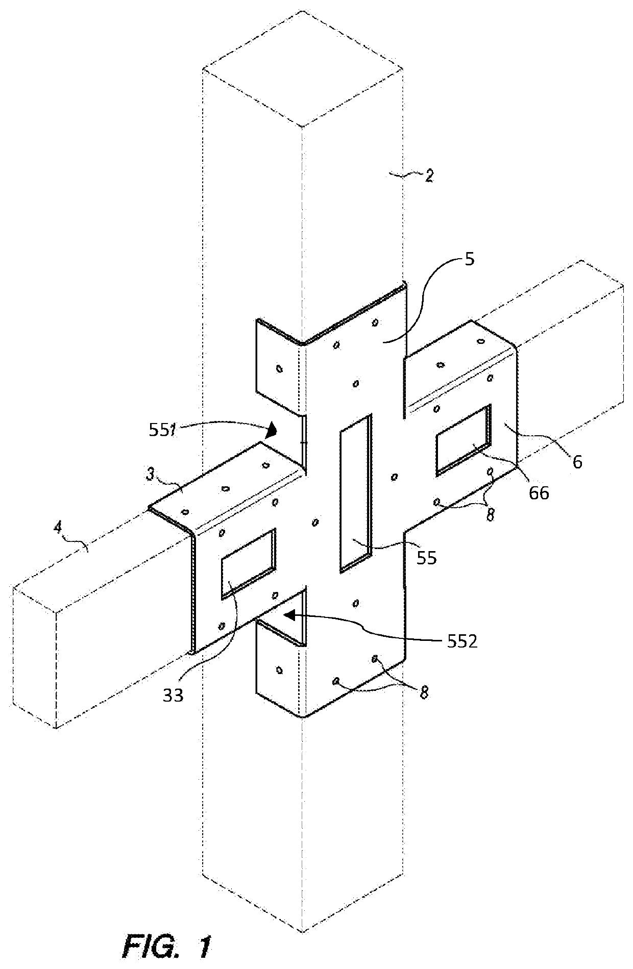
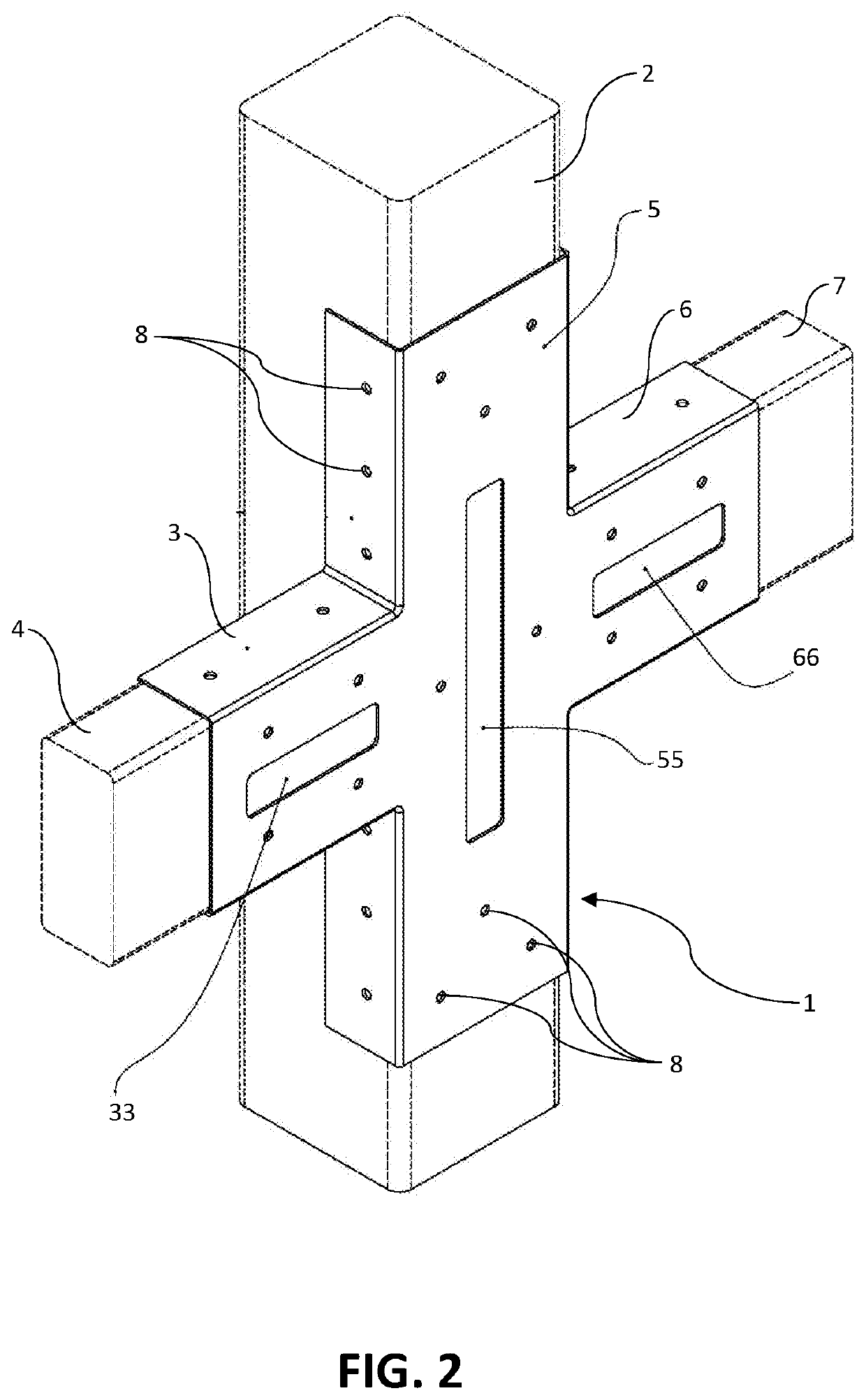
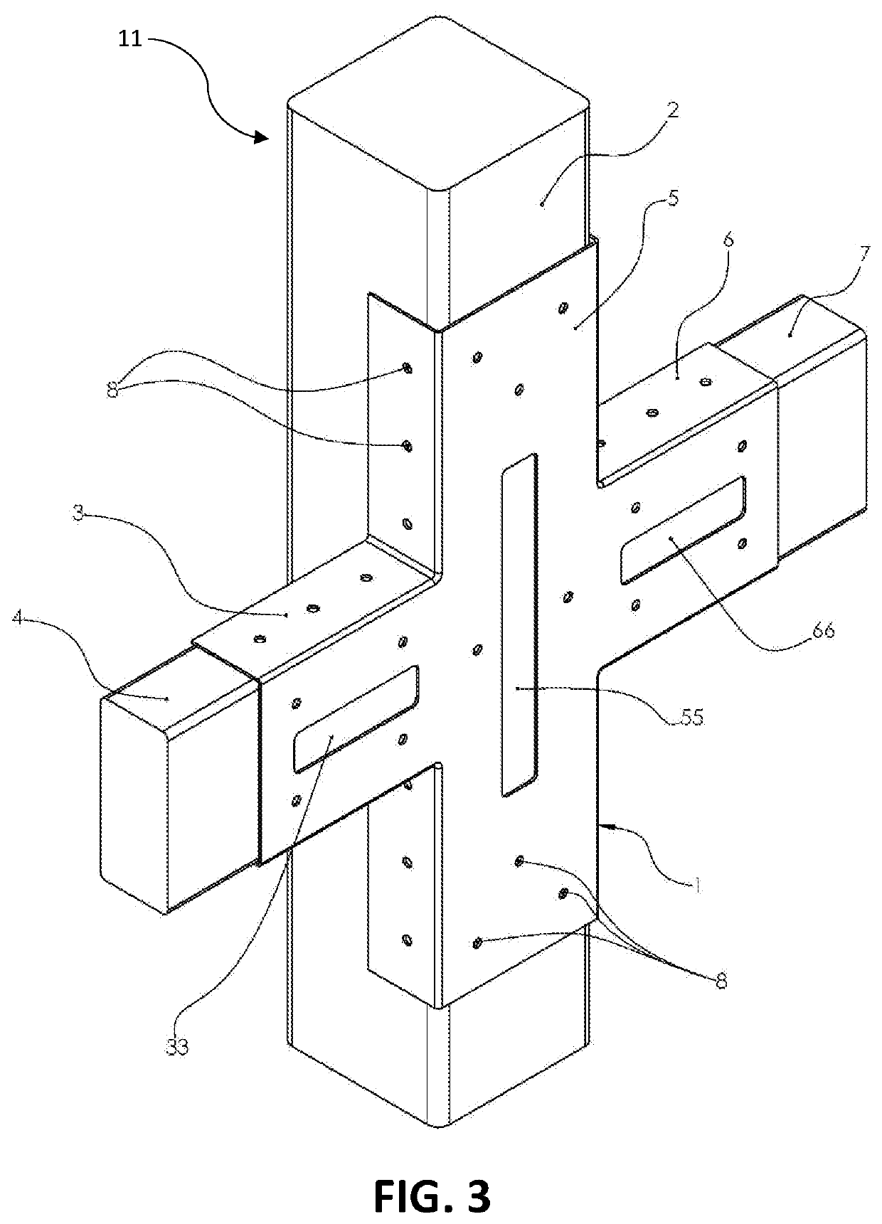
[0020]In a preferred embodiment as illustrated in FIG. 2, the present invention comprises fence brace 1 for securing at least one fence rail 4 to fence post 2 including first fence rail brace member 3 adapted to connect to two or more sides of first fence rail 4. First fence rail brace member 3 may be fused to a first side of fence post brace member 5 wherein fence post brace member 5 is adapted to connect to two or more sides of fence post 2. The fence rail may be rectanguloid. As used herein, the term “rectanguloid” means a solid (3-dimensional) object which has six faces that are rectangles. It has the same cross-section along a length. As used herein, “rectanguloid” is the same as a rectangular prism. A rectanguloid may be though of as a 3-dimensional version of a rectangle or a square. The herein disclosed fence brace system may further include second fence rail brace member 6 fused to a second side of fence post brace member 5, wherein second fence rail brace member 6 is adapt...


PUM


Abstract

The present invention comprises a brace adapted to secure one or more fence rails to a fence post. The present invention brace may optionally be installed onto an existing fence or on a new fence. The invention includes a first fence rail brace member adapted to connect to two or more sides of a first fence rail, a second fence rail brace member adapted to connect to two or more sides of a second fence rail, and a fence post member adapted to connect to two or more sides of a fence post. The fence post brace member may form a picket fastener slot for use in affixing a picket to the fence post. The fence post brace system may be adapted for use with cylindrical fence posts or rectangular fence posts.

Description

CROSS-REFERENCES TO RELATED APPLICATIONS[0001]This non-provisional utility application is a continuation-in-part (CIP) application of the pending U.S. application Ser. No. 14 / 863,793 titled “Fence Brace System” and originally filed Sep. 24, 2015, and of the pending U.S. application Ser. No. 15 / 856,635 titled “Fence Brace System” and originally filed Dec. 28, 2017 (pending U.S. application Ser. No. 15 / 856,635 is a divisional application of pending U.S. application Ser. No. 14 / 863,793), which are hereby incorporated in their entirety by reference.STATEMENTS AS TO THE RIGHTS TO INVENTIONS MADE UNDER FEDERALLY SPONSORED RESEARCH OR DEVELOPMENT[0002]Not applicable.REFERENCE TO A “SEQUENCE LISTING,” A TABLE, OR A COMPUTER PROGRAM LISTING APPENDIX SUBMITTED ON A COMPACT DISK[0003]Not applicable.BRIEF DESCRIPTION OF THE INVENTION[0004]The present invention relates to the field of fences. More particularly, the present invention relates to a system for providing structural support for fences...

Claims


Application Information

Patent Timeline
Patent Type & Authority Patents(United States)
IPC IPC(8): E04H17/14E04H17/20
CPCE04H17/1421E04H17/1443E04H17/20E04H17/1434E04H2017/1473E04H2017/146E04H2017/1482E04H17/146E04H17/1473E04H17/1452E04H17/1417E04H17/1447E04H17/143E04H17/1439E04H17/1482
Inventor CRANDALL, FONDACRANDALL, JOSEPH
Owner CRANDALL FONDA
Learn More