Leakage detection device

Active Publication Date: 2020-09-01
SUBARU CORP
View PDF25 Cites 3 Cited by
  • Summary
  • Abstract
  • Description
  • Claims
  • Application Information

AI Technical Summary

Benefits of technology

[0007]It is desirable to provide a leakage detection device capable of comprehensively detecting leakage that occurs in a PCV passage of an engine.
[0010]A second valve capable of adjusting a flow rate of blow-by gas that to be delivered from the crank chamber to the scavenging line may further be provided.

Problems solved by technology

However, a method for comprehensively detecting the leakage that occurs in any of these passages for constituting the PCV system (hereinafter simply referred to as a PCV passage) has not been suggested.

Method used


Image

  • Leakage detection device
  • Leakage detection device
  • Leakage detection device

Examples


Embodiment Construction

[0019]A detailed description will hereinafter be made on a preferred implementation of the present invention with reference to the accompanying drawings. Dimensions, materials, other specific numerical values, and the like described in such an implementation are merely illustrative to facilitate understanding of the invention and thus do not limit the present invention unless otherwise particularly noted. Note that, in this specification and the drawings, an overlapping description will not be made on elements that have substantially the same function or configuration and will be denoted by the same reference sign. In addition, elements that are not directly related to the present invention will not be illustrated.

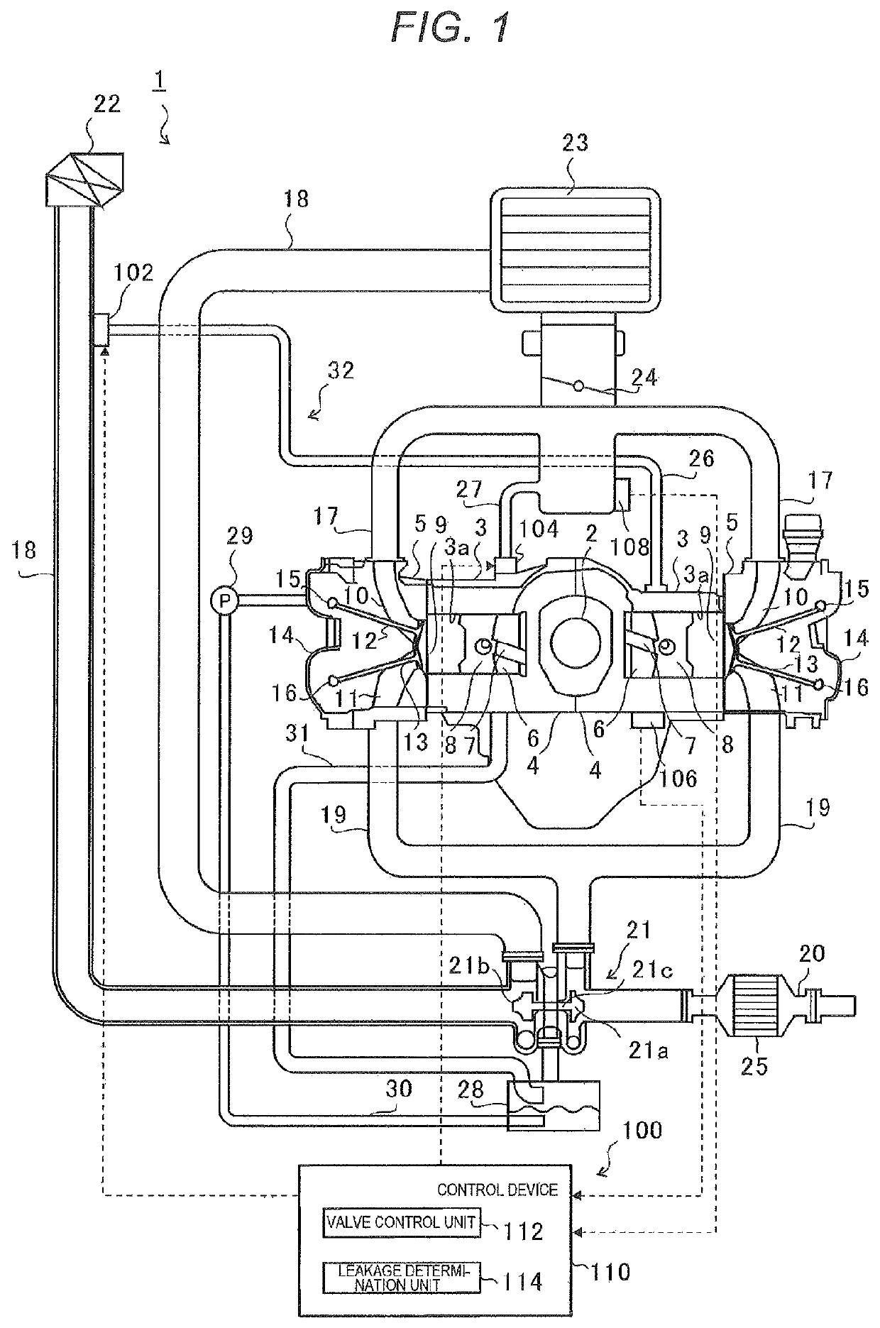
[0020]FIG. 1 is a schematic view of an engine 1 that includes a leakage detection device 100 of the present invention. Initially, a schematic configuration of the engine 1 will be described. Then, a configuration of the leakage detection device 100 will be described.

[0021]...


PUM


Abstract

A leakage detection device detects leakage in a PCV passage that at least includes a scavenging line that communicates between a crank chamber of an engine and a portion of an intake passage of the engine that is on a downstream side of a throttle valve and a fresh air line that communicates between the crank chamber and a portion of the intake passage that is on an upstream side of the throttle valve. The leakage detection device includes a pressure measurement, a first valve and a leakage determination unit. The pressure measurement unit measures pressure in the PCV passage. The first valve opens / closes the fresh air line. The leakage determination unit determines presence or absence of leakage in the PCV passage on a basis of the pressure in the PCV passage at a time when the first valve is closed.

Description

CROSS-REFERENCE TO RELATED APPLICATIONS[0001]The present application claims priority from Japanese Patent Application No. 2016-054526 filed on Mar. 17, 2016, the entire contents of which are hereby incorporated by reference.BACKGROUND1. Technical Field[0002]The present invention relates to a leakage detection device for detecting leakage that occurs in a passage for constituting a PCV system of an engine.2. Related Art[0003]Conventionally, an engine includes a positive crankcase ventilation (PCV) system for guiding blow-by gas, which flows from a combustion chamber and is leaked into a crankcase through a gap between a cylinder and a piston, to an intake passage.[0004]This PCV system returns the blow-by gas that contains nitrogen oxides (NOx), carbon monoxide (CO), hydrocarbons (HC), and the like to the intake passage of the engine via a blow-by gas passage and thereby prevents release of the blow-by gas to the atmosphere.[0005]When leakage occurs in the blow-by gas passage, the blo...

Claims


Application Information

Patent Timeline
Patent Type & Authority Patents(United States)
IPC IPC(8): F02B25/06F02M25/06F01M13/02F02D41/22
CPCF02D41/22F02M25/06F01M13/023F02D2250/08F02D2200/0406F01M2013/027Y02T10/12F01M11/10F01M2013/0083Y02T10/40
Inventor TAKAHASHI, DAISUKESHIWA, DAIKI
Owner SUBARU CORP
Why Eureka
Try Eureka