High performance bicycle crank

a high-performance, crank technology, applied in the direction of cycle equipment, mechanical control devices, instruments, etc., can solve the problems of crank deflection, greatest load, crank added strength and stiffness that the resin alone cannot provide, etc., to achieve the effect of low material cost, low addition of weight, and relatively easy joining to the foam cor

Inactive Publication Date: 2005-07-07
COMPOSITECH
View PDF19 Cites 24 Cited by
  • Summary
  • Abstract
  • Description
  • Claims
  • Application Information

AI Technical Summary

Benefits of technology

[0025] One feature of the present invention is that it incorporates a curable foam material. This feature has the advantage of providing a foam around which the uncured carbon fiber sheets can be wrapped for giving form and shape to the carbon fiber exoskeleton. This form giving quality is achieved by the foam at a very low material cost, and with a very low addition of weight.
[0026] Another feature of the present invention is that a pedal lug is added to the foam core after the first molding process. This feature has the advantage of enabling the pedal lug to be joined to the foam core quite easily, while removing the design constraints inherent in prior systems that joined a pedal lug to a foam core in a unitary molding process.

Problems solved by technology

The carbon fibers give the final crank added strength and stiffness that the resin by itself can not provide.
Initial pedaling, climbing or sprinting result in the greatest loads.
This force exerted by the cyclist when pedaling results in two types of deflections of the crank.
First, the hollow carbon fiber construction makes the crank significantly lighter than standard metal cranks.
One drawback with the 1997 ZIPP crank is its incompatibility with one of the more popular spline drive systems used on bicycles.
Another drawback with the 1997 ZIPP crank is that it is difficult to manufacture, requiring the three separate components be molded out of carbon fiber, and then line welded to each other and bonded together.
This process was labor-intensive and time consuming.

Method used


Image

  • High performance bicycle crank
  • High performance bicycle crank
  • High performance bicycle crank

Examples


Embodiment Construction

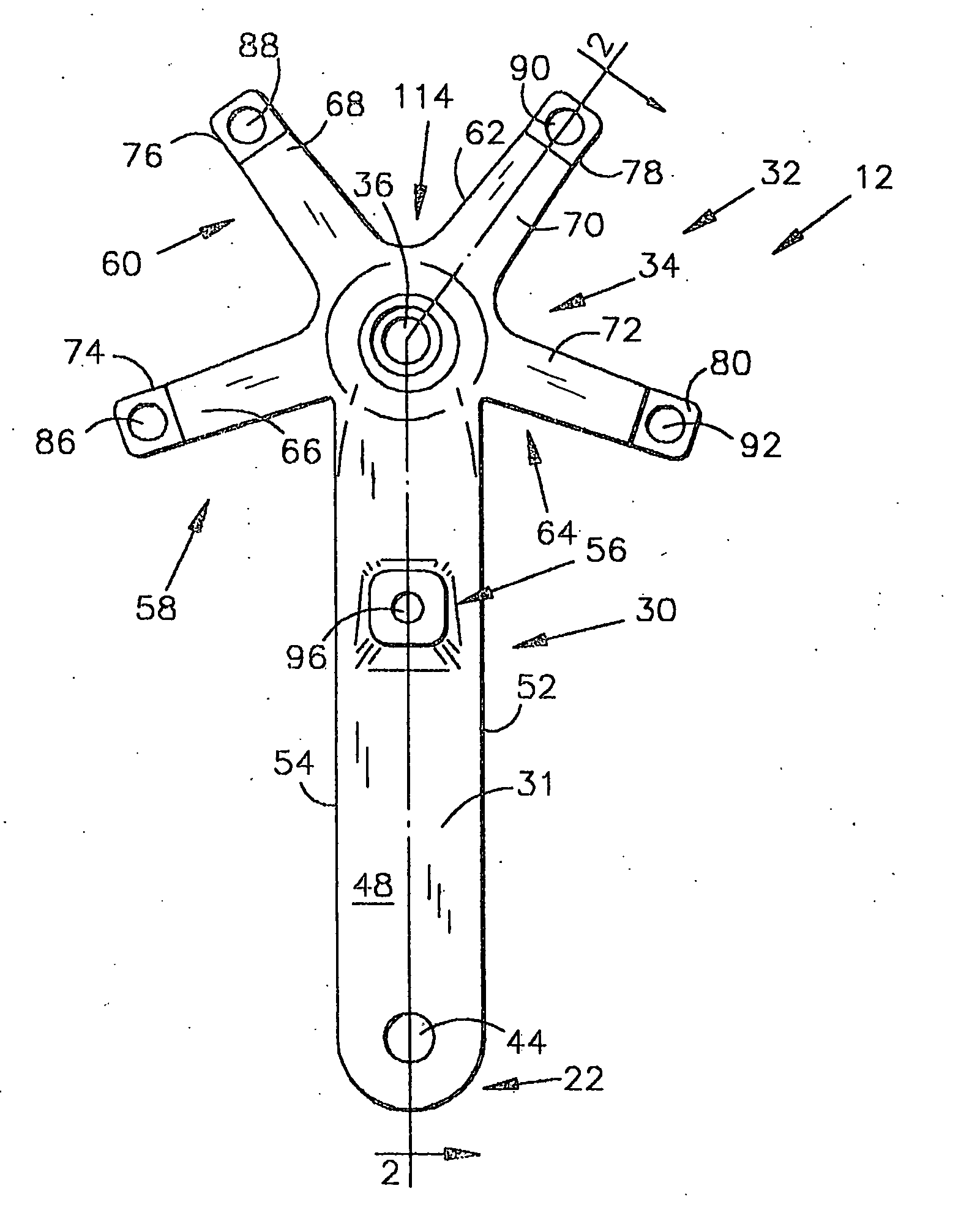
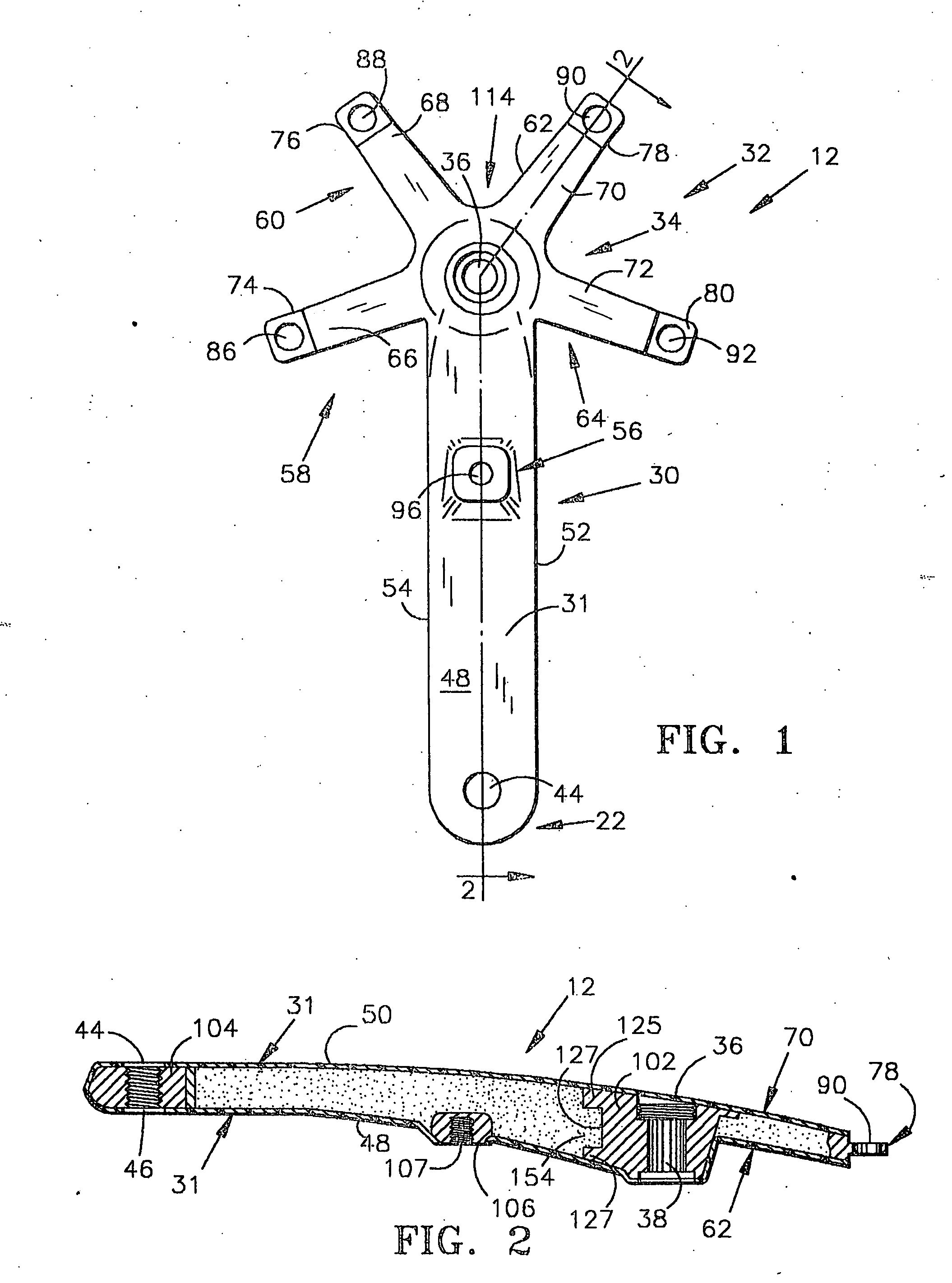
[0040] Referring first to FIG. 12, a bicycle 10 is shown with both a drive side crank 12 and a non drive side (slave) crank 16 of the present invention assembled thereto. Each crank 12, 16 is fixedly attached to the bottom bracket spindle axle (not shown) which is rotatably journaled in the bottom bracket spindle housing 14. The chain drive sprocket, (chain ring) 18 is fixedly attached to drive side crank 12 for rotation about an axis defined by the bottom bracket spindle. The pedals 20a, 20b are rotatably coupled to the distal end 22 of crank 12, 14 by a bearing assembly containing pedal coupling axle rods 21a, 21b, to permit the pedals to rotate about an axis defined by the respective pedal coupling rods 21a, 21b. Drive side crank 12 and non-drive side crank 14 rotate about the axis of rotation of the bottom bracket spindle (not shown) during a pedal stroke. This rotation results in a rotation of chain ring 18 about the same spindle axis which in turn rotates the rear wheel of the...


PUM


Abstract

A carbon fiber bicycle crank includes an axle lug, having a portion for receiving a crank axle. A foam core is coupled to the axle lug during a first molding process. A pedal engaging lug is coupled to the foam core after the completion of the first molding process, and a carbon fiber composite material exoskeleton is coupled to and disposed exteriorly of the axle lug, foam core and pedal lug.

Description

I. STATEMENT OF PRIORITY [0001] This utility patent application claims priority to U.S. Provisional Patent Application Ser. No. 60 / 322,870, filed 17 Sep. 2001.II. TECHNICAL FIELD [0002] The present invention relates to bicycle cranks, and more particularly to carbon fiber bicycle cranks. The carbon fiber crank has improved strength over metal cranks and has a significantly lower weight. III. BACKGROUND OF INVENTION [0003] When an athlete first takes up a new sport she typically buys moderately priced equipment with decent performance characteristics. As her abilities improve she looks for ways to increase her performance and hence her competitiveness. Upgrading equipment is one method of increasing performance. [0004] The vast majority of bicycles purchased are off-the-shelf bikes as opposed to custom bikes. A custom bike is created by buying individual components and assembling these components together into a complete bike. As a cyclist becomes more involved in the sport, it is ty...

Claims


Application Information

Patent Timeline
Patent Type & Authority Applications(United States)
IPC IPC(8): G05G1/30B62K19/16B62M3/00
CPCB62K19/16Y10T74/2164B62M3/00
Inventor ORDING, ANDREWBARKER, AARON
Owner COMPOSITECH
Why Eureka
Try Eureka