
Systems and methods for delivering an implantable device

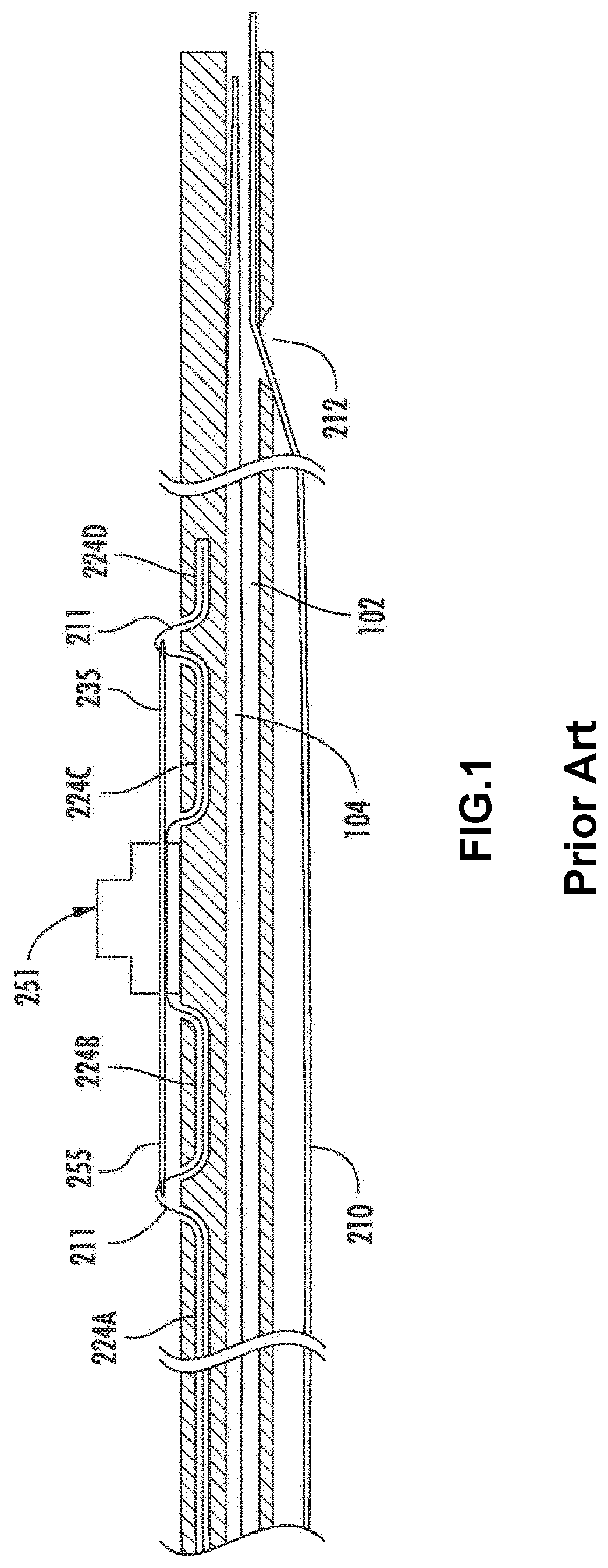
a technology of implantable devices and systems, applied in the field of systems and methods for delivering implants, can solve the problems of device dislocation in the main pulmonary artery, increased risk, and difficulty in establishing landmarks for delivering devices in the pulmonary artery,

Active Publication Date: 2020-09-15
OHIO STATE INNOVATION FOUND
View PDF16 Cites 7 Cited by
  • Summary
  • Abstract
  • Description
  • Claims
  • Application Information

AI Technical Summary

Benefits of technology

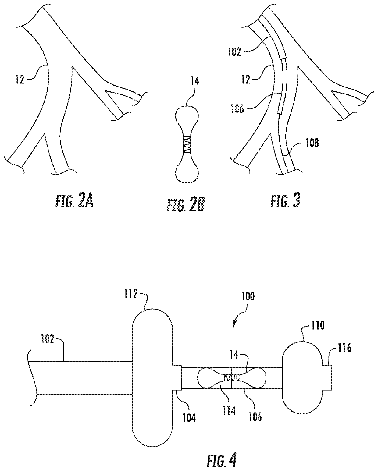
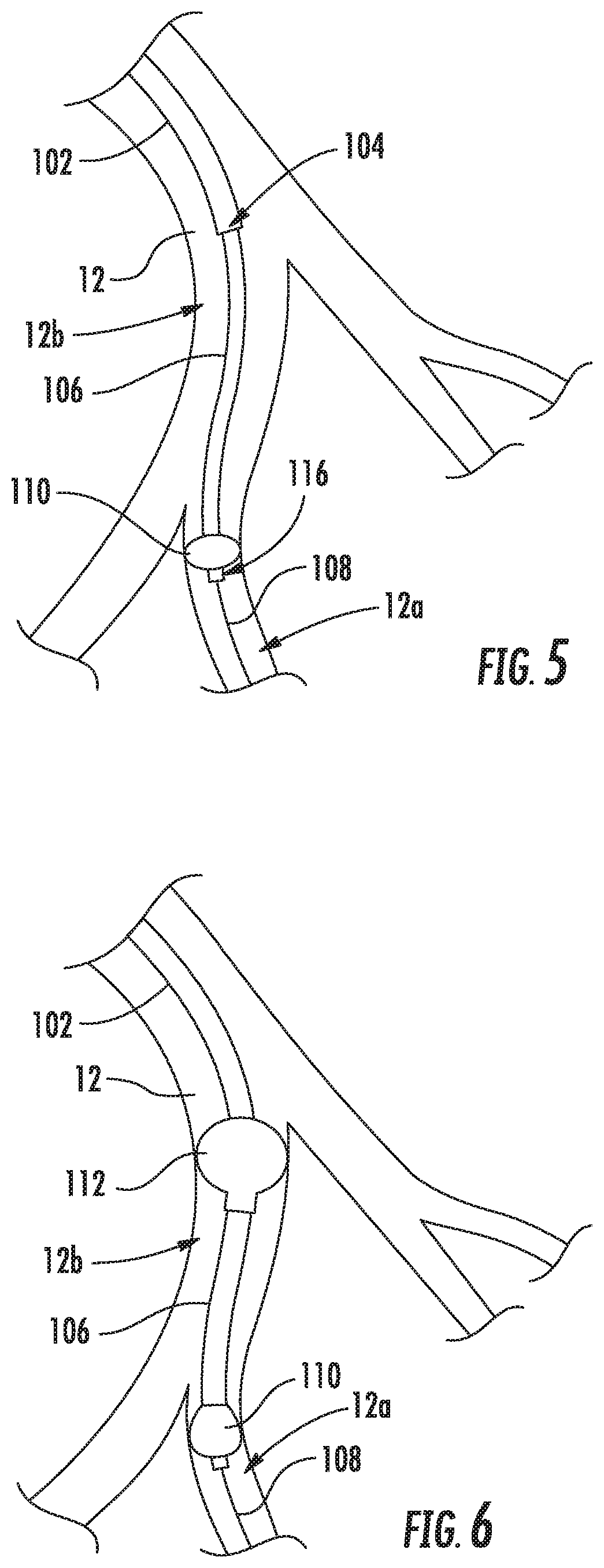
[0007]Described herein are various systems and methods of delivering an implantable device within a vessel of a patient. For example, in certain implementations, the delivery system includes an outer catheter having a distal tip and an inner support member disposed within the outer catheter. The inner support member includes an anchor member disposed adjacent a distal tip of the inner support member and a support portion axially inward of the anchor member. The support portion is configured for supporting an implantable device thereon. A diameter of the anchor member corresponds to a diameter of a portion of a vessel in which the anchor member is to be disposed. The anchor member is configured to be lodged in the portion of the vessel to locate an intended position of the anchor member and to prevent movement of the inner support member relative to the vessel during release of the implantable device.

Problems solved by technology

Therefore, establishing landmarks for delivering devices within the pulmonary artery can be very difficult.
And, if the device is deployed proximally of the branch of interest, there is an increased risk that the device will dislodge in the main pulmonary artery, where it cannot be retrieved.

Method used


Image

  • Systems and methods for delivering an implantable device
  • Systems and methods for delivering an implantable device
  • Systems and methods for delivering an implantable device

Examples


Embodiment Construction

[0022]Described herein are various systems and methods of delivering an implantable device within a vessel of a patient. For example, the device may be a hemodynamic sensor, such as a CARDIOMEMS sensor, and delivered to a portion of a patient's left pulmonary artery, according to certain implementations. A portion of the left pulmonary artery 12 is shown in FIG. 2A, and a hemodynamic sensor 14 is shown in FIG. 2B. However, other implementations may be configured for delivering other types of implantable devices, and those devices may be intended for other vessels within the patient's body.

[0023]The delivery system may include, for example, an outer catheter having a distal tip and an inner support member, such as an inner catheter, disposed within the outer catheter. The inner support member includes an anchor member adjacent a distal tip of the inner support member and a support portion axially inward of the anchor member. The support portion is configured for supporting an implant...


PUM


Abstract

The delivery system may include, for example, an outer catheter having a distal tip and an inner support member, such as an inner catheter, disposed within the outer catheter. The inner support member includes an anchor member adjacent a distal tip of the inner support member and a support portion axially inward of the anchor member. The support portion is configured for supporting an implantable device thereon. A diameter of the anchor member corresponds to a diameter of a portion of a vessel in which the anchor member is to be disposed. The anchor member is configured to be lodged in the portion of the vessel to locate an intended position of the anchor member and to prevent movement of the inner support member relative to the vessel during release of the implantable device.

Description

CROSS-REFERENCE TO RELATED APPLICATIONS[0001]This application is a national stage application filed under 35 U.S.C. § 371 of PCT / US2016 / 037037 filed Jun. 10, 2016, which claims the benefit of U.S. Provisional Application Ser. No. 62 / 174,267, filed Jun. 11, 2015, the disclosures of which are hereby incorporated by reference in its entirety their entireties.BACKGROUND[0002]CARDIOMEMS, which is owned by St. Jude Medical, is a new FDA-approved device used for monitoring pulmonary artery pressures in patients with a history of systolic or diastolic heart failure and prior heart failure hospitalization within one year. The data from the device is transmitted wirelessly to a secure website and reviewed by health professionals. The sensor is very durable as it does not require a battery and does not have any moving parts. The sensor allows volume status of millions of patients worldwide to be managed more accurately and precisely. Various implementations of the CARDIOMEMS device are describ...

Claims


Application Information

Patent Timeline
Patent Type & Authority Patents(United States)
IPC IPC(8): A61B5/0215A61M25/10A61B5/00A61M25/04
CPCA61M25/10A61B5/6882A61B5/6886A61B5/6853A61B5/0215A61B5/6876A61M25/04A61M2025/1015A61B2560/066A61M2025/1054A61B5/0031
Inventor KAHWASH, RAMI
Owner OHIO STATE INNOVATION FOUND
Learn More