Encoder unit, angle measuring method, and robot
a technology applied in the field of encoder unit and angle measurement method, can solve the problems of difficult enhancement of detection accuracy and inability to sufficiently reduce errors
- Summary
- Abstract
- Description
- Claims
- Application Information
AI Technical Summary
Benefits of technology
Problems solved by technology
Method used
Image

Examples
first embodiment
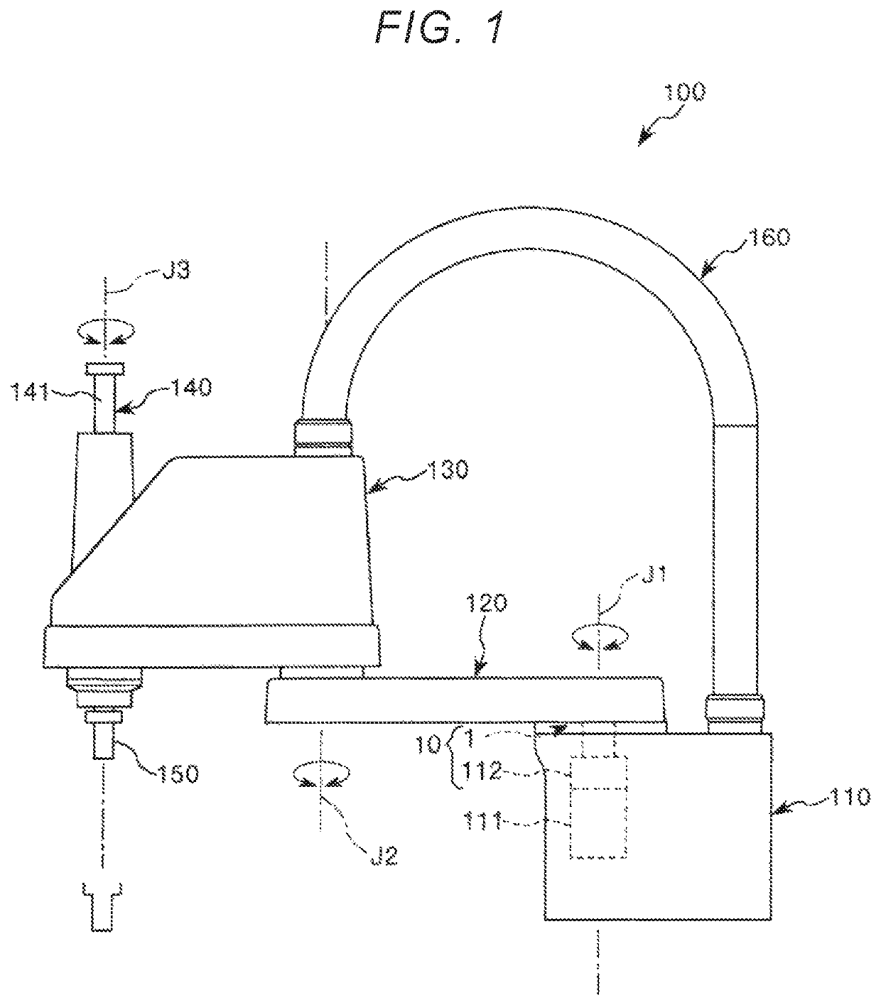
[0045]Hereinafter, the encoder unit 10 will be described in detail. Hereinafter, a case where the encoder unit 10 is installed in the robot 100 will be described as an example.
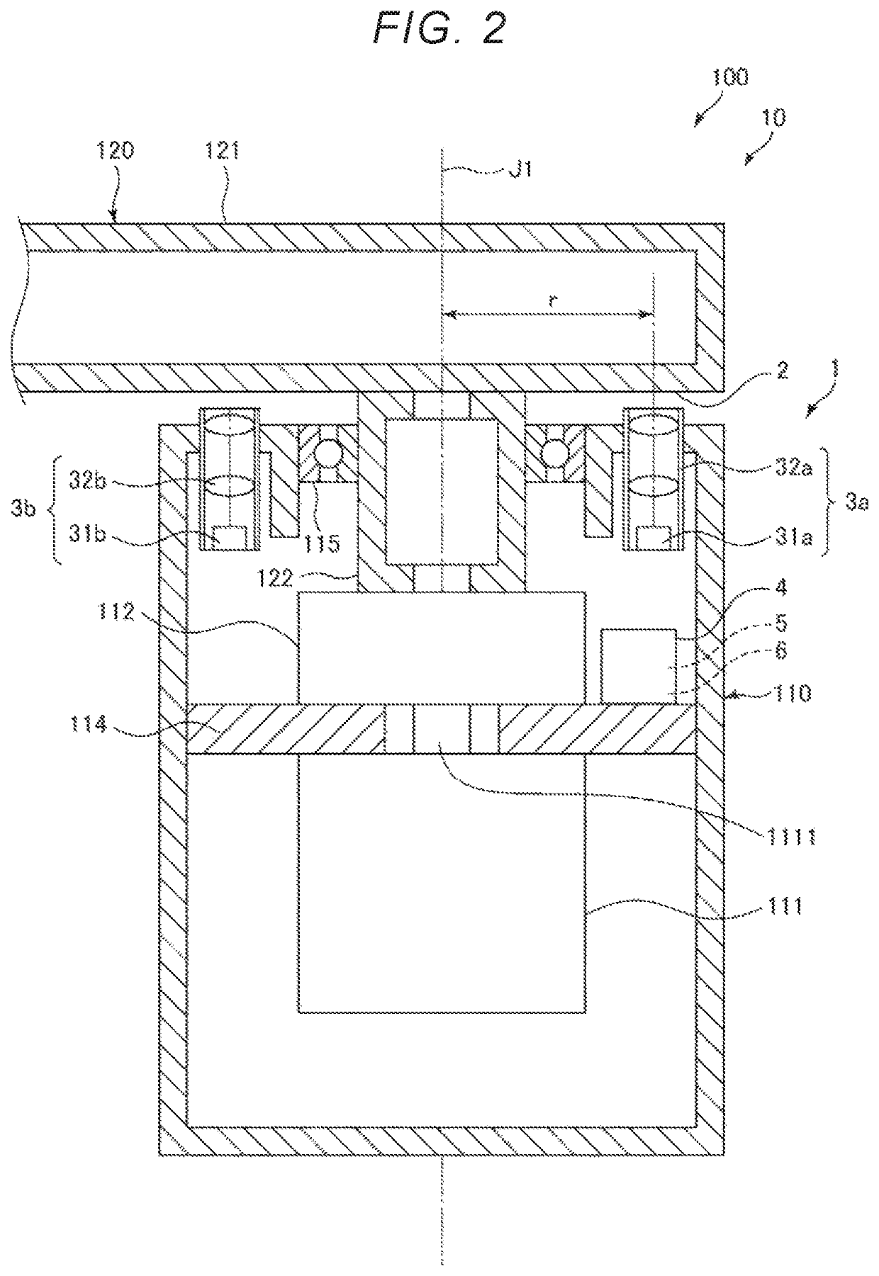
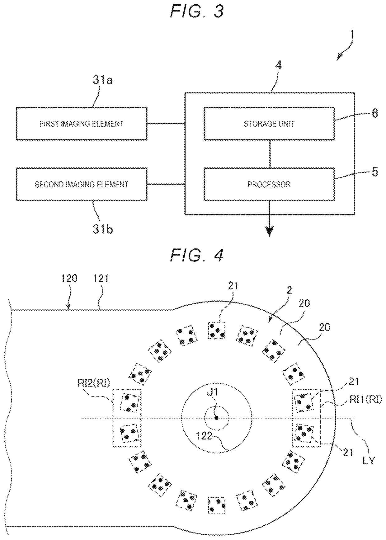
[0046]FIG. 2 is a sectional view illustrating the encoder unit according to a first embodiment of the invention. FIG. 3 is a block diagram illustrating the encoder of the encoder unit. FIG. 4 is a view for illustrating a scale portion included in the encoder of the encoder unit. In addition, in the drawings, for convenience of description, a scale of portions is appropriately changed, a scale in a configuration illustrated in the drawings is not necessarily equal to an actual scale, or portions are appropriately omitted in the drawing.
[0047]As illustrated in FIG. 2, the base 110 of the robot 100 described above includes a support member 114 that supports the motor 111 and the speed reducer 112 and houses the motor 111 and the speed reducer 112. The first arm 120 is provided on the base 110 so as to be rotation...
second embodiment
[0130]FIG. 21 is a schematic diagram illustrating a relationship between an effective visual field region and a movement locus of the scale portion in a second embodiment of the invention. FIG. 22 is a diagram for illustrating a correction factor in the second embodiment of the invention. FIG. 23 is a flowchart illustrating a flow of obtaining the correction factor in the second embodiment of the invention.
[0131]Hereinafter, the second embodiment is described by focusing on differences from the embodiment described above, and the same description is omitted.
[0132]The embodiment is the same as the first embodiment described above except that the correction factor of an inclination of the imaging region is used when the rotation angle is calculated.
[0133]In the first embodiment described above, a case where the tangential line to the arc C at the intersection point between the center line LY and the arc C as the locus of the mark 21 is parallel to the X axis is described. However, an ...
third embodiment
[0143]FIG. 24 is a perspective view illustrating a robot according to a third embodiment of the invention.
[0144]Hereinafter, a side of the base 210 of a robot 100C is referred to as a “proximal end side”, and a side of the end effector is referred to as a “distal end side”.
[0145]Hereinafter, the third embodiment is described by focusing on differences from the embodiments described above, and the same description is omitted.
[0146]The robot 100C illustrated in FIG. 24 is a vertical articulated (six-axis) robot. The robot 100C includes the base 210 and a robotic arm 200, and the robotic arm 200 includes a first arm 220, a second arm 230, a third arm 240, a fourth arm 250, a fifth arm 260, and a sixth arm 270. The arms are connected in this order from the proximal end side toward the distal end side. Although not illustrated, the end effector such as a hand, which grips is precision measuring equipment, a component, or the like, is detachably attached in a distal portion of the sixth a...
PUM
 Abstract
Description
Claims
Application Information
 - R&D
- Intellectual Property
- Life Sciences
- Materials
- Tech Scout
- Unparalleled Data Quality
- Higher Quality Content
- 60% Fewer Hallucinations
Browse by: Latest US Patents, China's latest patents, Technical Efficacy Thesaurus, Application Domain, Technology Topic, Popular Technical Reports.
© 2025 PatSnap. All rights reserved.Legal|Privacy policy|Modern Slavery Act Transparency Statement|Sitemap|About US| Contact US: help@patsnap.com