Ramp door operating mechanism

a technology of operating mechanism and ramp door, which is applied in the directions of transportation and packaging, transportation items, loading/unloading vehicle arrangment, etc., can solve the problems of both inconvenience and potential danger

Active Publication Date: 2020-10-13
LIPPERT COMPONENTS
View PDF31 Cites 0 Cited by
  • Summary
  • Abstract
  • Description
  • Claims
  • Application Information

AI Technical Summary

Benefits of technology

[0005]It would be desirable to provide a ramp door that could be pivoted between a closed position, a deck position, and a ramp position without requiring a user to disconnect any support cables. In some embodiments, a cam or lever connected to the door tether is selectively releasable manually or by a solenoid to enable the ramp door to further pivot from the deck position to the ramp position without requiring the tether to be disconnected from the door. In some embodiments, a slider assembly is selectively releasable for displacement in a track to similarly enable the ramp door to further pivot from the deck position to the ramp position.
[0008]In some embodiments, the tether extender may include a track connectable to the structure and a slider displaceable in the track between a retracted position and an extended position. In this context, the second tether is fixed to the slider, and the slider may be lockable in the retracted position. The tether extender may additionally include a keyway adjacent the track, where the slider may include a locking collar that is sized to fit through the keyway but not into the track and a sliding surface that is sized to fit into the track. The slider is displaceable laterally relative to the track between a lock position and a release position. In the lock position, the locking collar may be positioned in the keyway and displacement of the slider in the track may be prevented, and in the release position, the sliding surface may be disposed in the track and the locking collar may be spaced from the keyway such that displacement of the slider in the track is permitted. The slider may be displaceable between the lock position and the release position by a solenoid actuator. The slider may additionally include a limit stop that is positioned to limit lateral displacement of the slider. The tether extender may additionally include a slider biasing mechanism acting on the slider and biasing the slider toward the retracted position.

Problems solved by technology

This is both inconvenient and potentially dangerous.

Method used


Image

  • Ramp door operating mechanism
  • Ramp door operating mechanism
  • Ramp door operating mechanism

Examples


Embodiment Construction

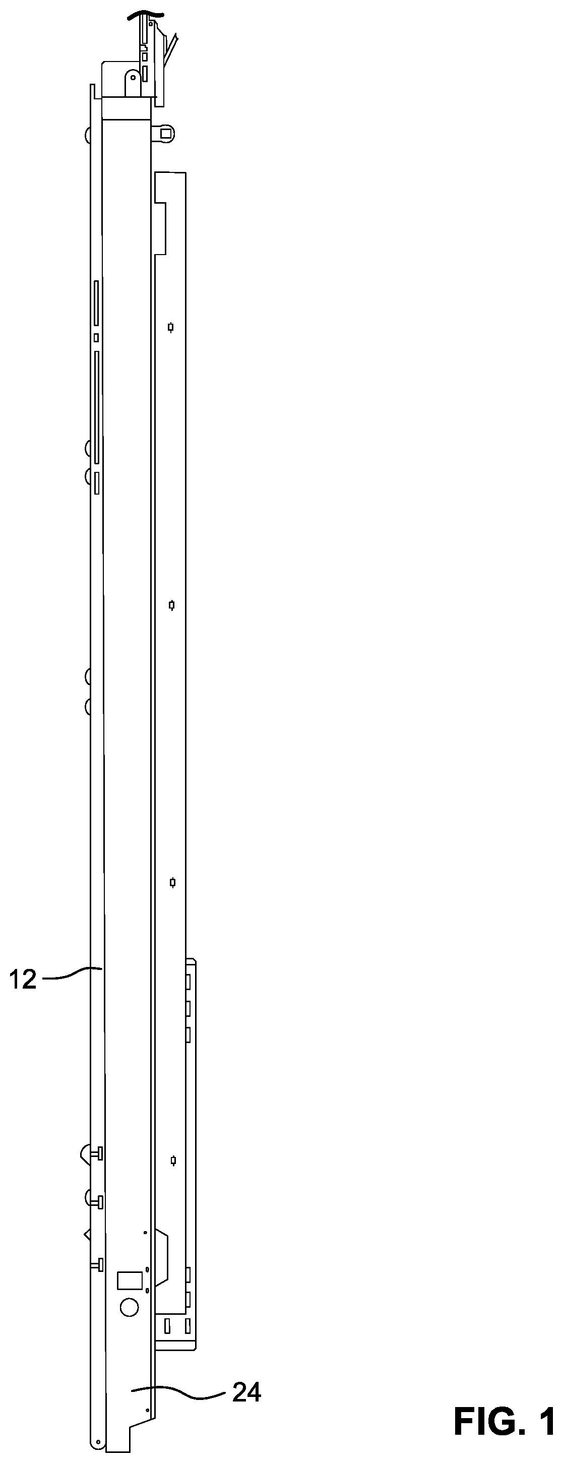
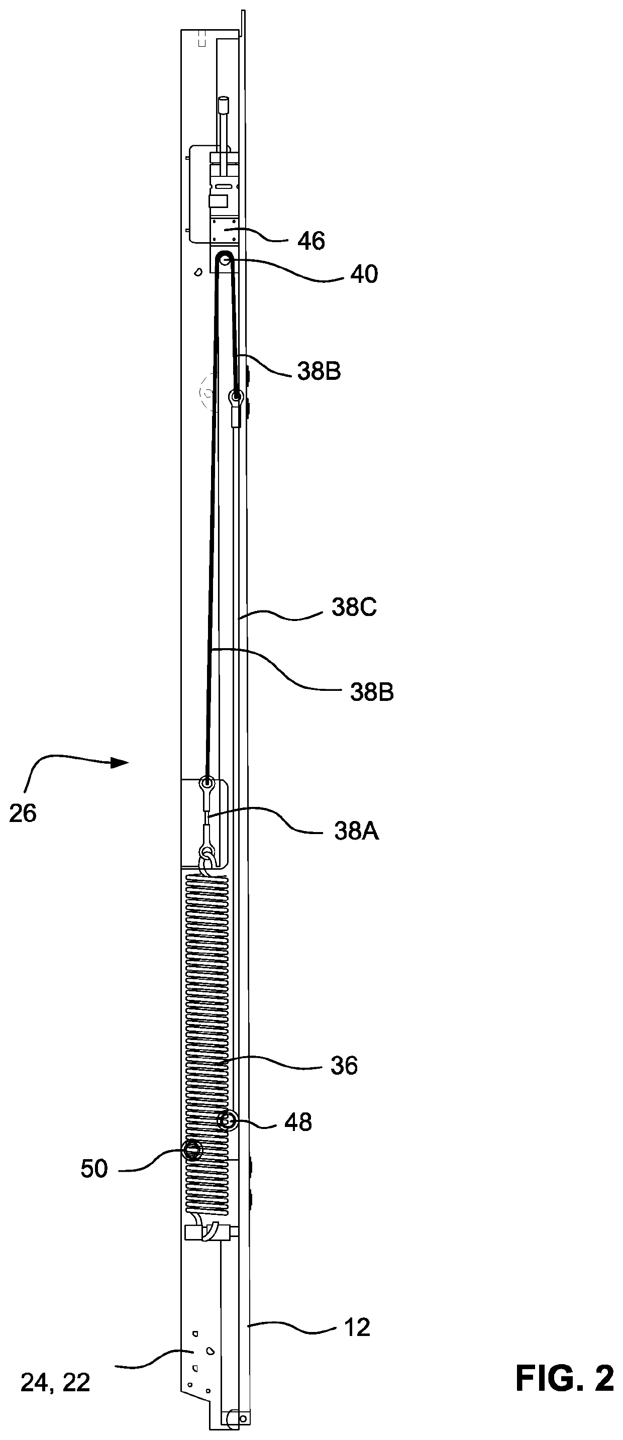
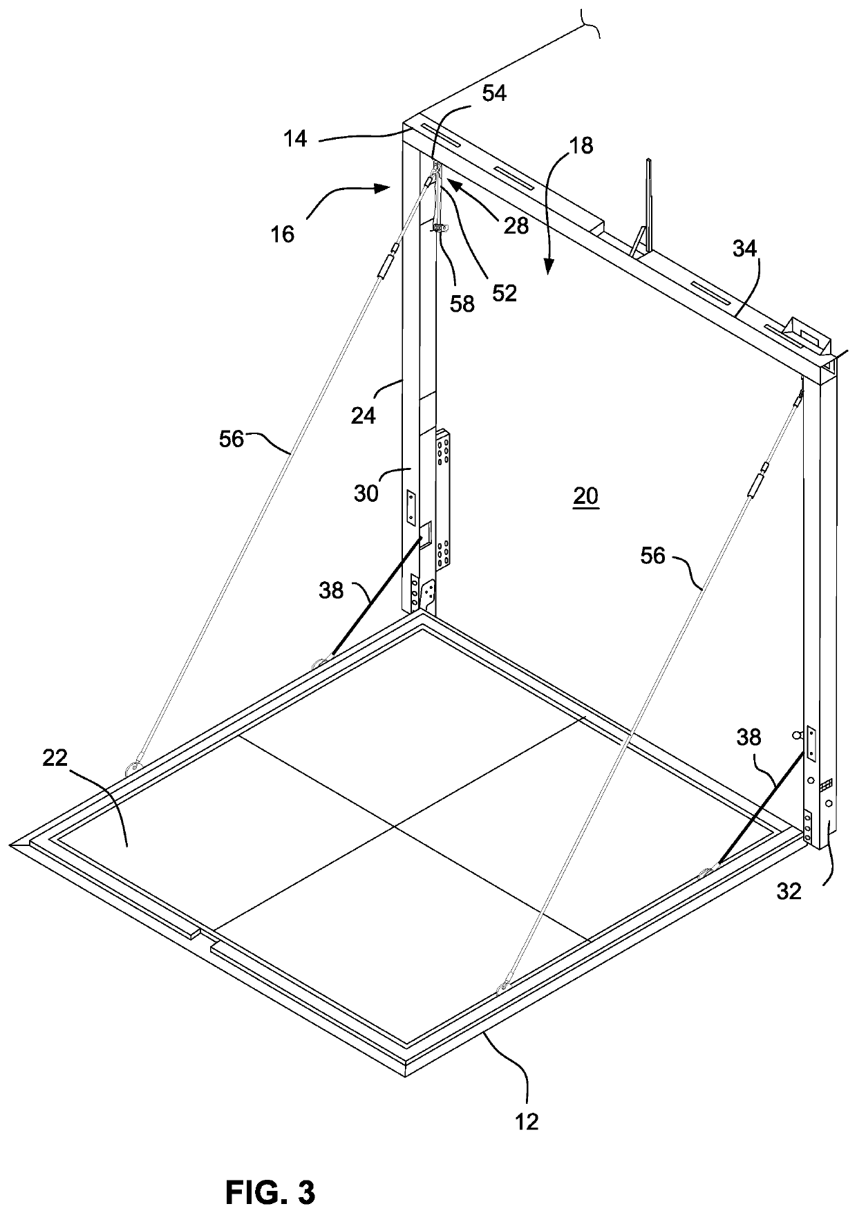
[0026]The drawings show illustrative embodiments of a mechanism 10 for operating a ramp door 12 pivotally connected to or otherwise pivotally associated with a structure 14. In an embodiment, the structure 14 may be a vehicular structure, for example, a recreational vehicle or trailer. The structure 14 includes an exterior wall 16 defining an opening 18, and a floor 20. The door 12 defines a load surface 22. The door 12 is pivotally connected to or associated with the structure 14 so that the door may be pivoted between a first position in which the door covers or occupies the opening 18, a second position in which the door load surface 22 is substantially parallel to the floor 20, and a third position pivotally further from the first position than the second position. When in the third position, the door 12 may provide contiguous access between the floor 20 and the ground G upon which the structure 14 may be situated.

[0027]The mechanism 10 includes a frame 24, a door actuation syst...


PUM


Abstract

An operating mechanism for a ramp door includes a door actuation system and a limit stop system. The actuation system is connected between the door and a frame or the vehicular structure directly and is operable to pivot the door between closed, deck, and ramp positions. The limit stop system selectively limits the pivoting of the door to a range between the closed and deck portion or to a range between the closed and ramp positions.

Description

CROSS-REFERENCES TO RELATED APPLICATIONS[0001]This application claims the benefit of U.S. Provisional Patent Application No. 62 / 631,233, filed Feb. 15, 2018, the entire content of which is herein incorporated by reference.STATEMENT REGARDING FEDERALLY SPONSORED RESEARCH OR DEVELOPMENT[0002](Not Applicable)BACKGROUND[0003]The present invention relates to a ramp door for a vehicular structure and, more particularly, to a ramp door operating mechanism that facilitates positioning of the ramp door among a closed position, a deck position, and a ramp position.[0004]It is known to provide a ramp door for a vehicular structure, for example, a recreational vehicle or trailer, with a ramp door that can be pivoted between a closed position, a deck position, and a ramp position. Such a ramp door may be suspended in the second (deck) position by one or more support cables extending between the ramp door and an upper portion of the vehicle. In order for the door to be lowered to the third positi...

Claims


Application Information

Patent Timeline
Patent Type & Authority Patents(United States)
IPC IPC(8): B60N2/00B60P1/43
CPCB60P1/435B60P1/436
Inventor ROTH, BRYAN J.ALBRECHT, JEFFREY K.BILANCIO, DOMINICKSKINNER, DAVID G.EVANS, SAMUEL
Owner LIPPERT COMPONENTS
Why Eureka
Try Eureka