Vacuum suction apparatus

a vacuum suction and vacuum technology, applied in the direction of electrical devices, manipulators, gripping heads, etc., can solve the problems of deformation and damage of workpieces, low workpiece product quality, etc., and achieve the effect of lowering the product quality of workpieces

Inactive Publication Date: 2013-04-04
SMC CORP
View PDF8 Cites 20 Cited by
  • Summary
  • Abstract
  • Description
  • Claims
  • Application Information

AI Technical Summary

Benefits of technology

[0006]Although in recent years the above-described vacuum suction apparatus have been used with the aim of transporting thin plate shaped workpieces such a solar panels, liquid crystal displays and the like, when such workpieces come into abutment against the suction surface of the porous body, chemical substances from the suction surface are

Problems solved by technology

Such suction tracks tend to lower the product quality of the workpieces.
Further, for example, in the event that the workpiece is h

Method used


Image

  • Vacuum suction apparatus
  • Vacuum suction apparatus
  • Vacuum suction apparatus

Examples


Embodiment Construction

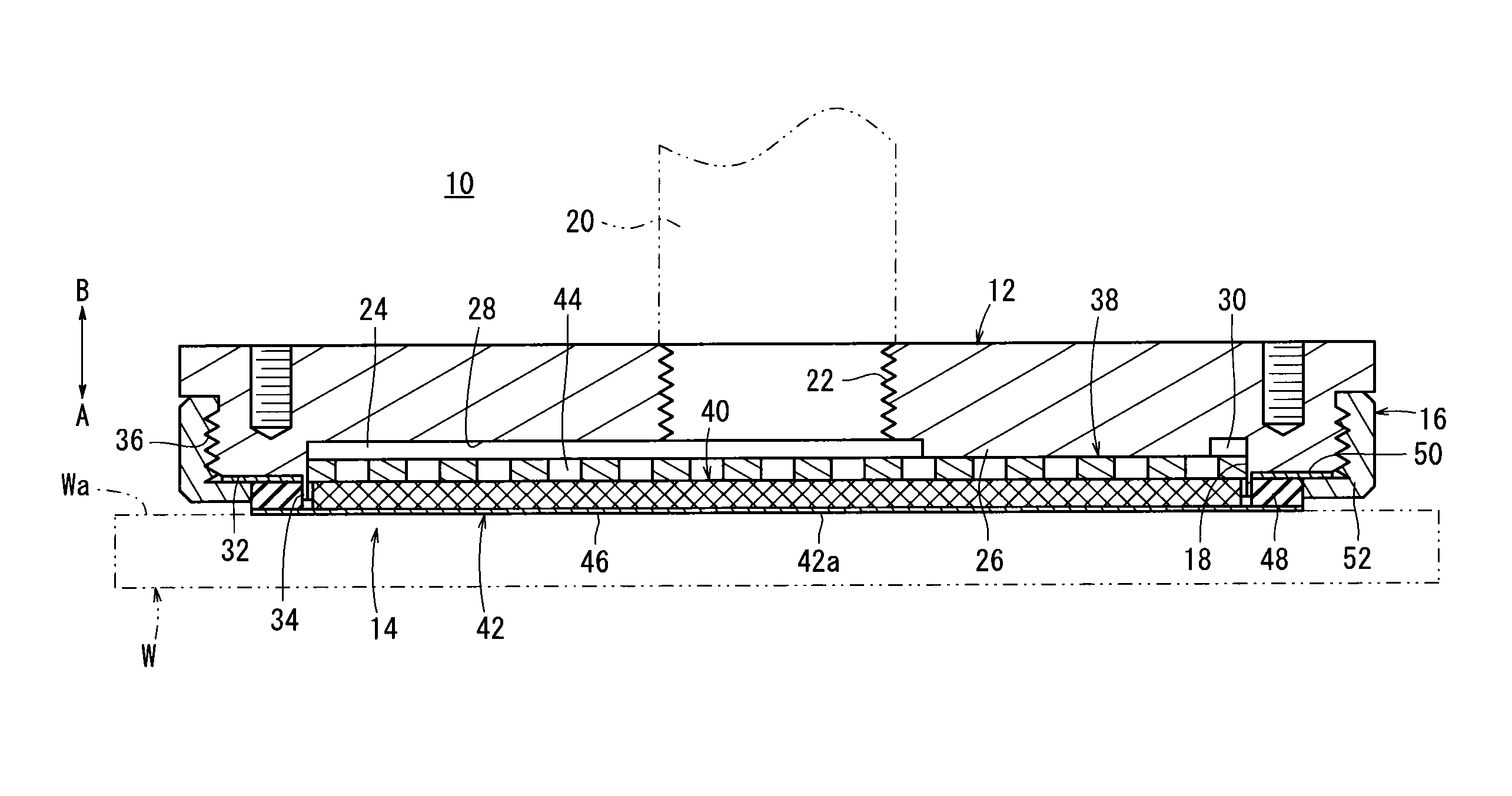
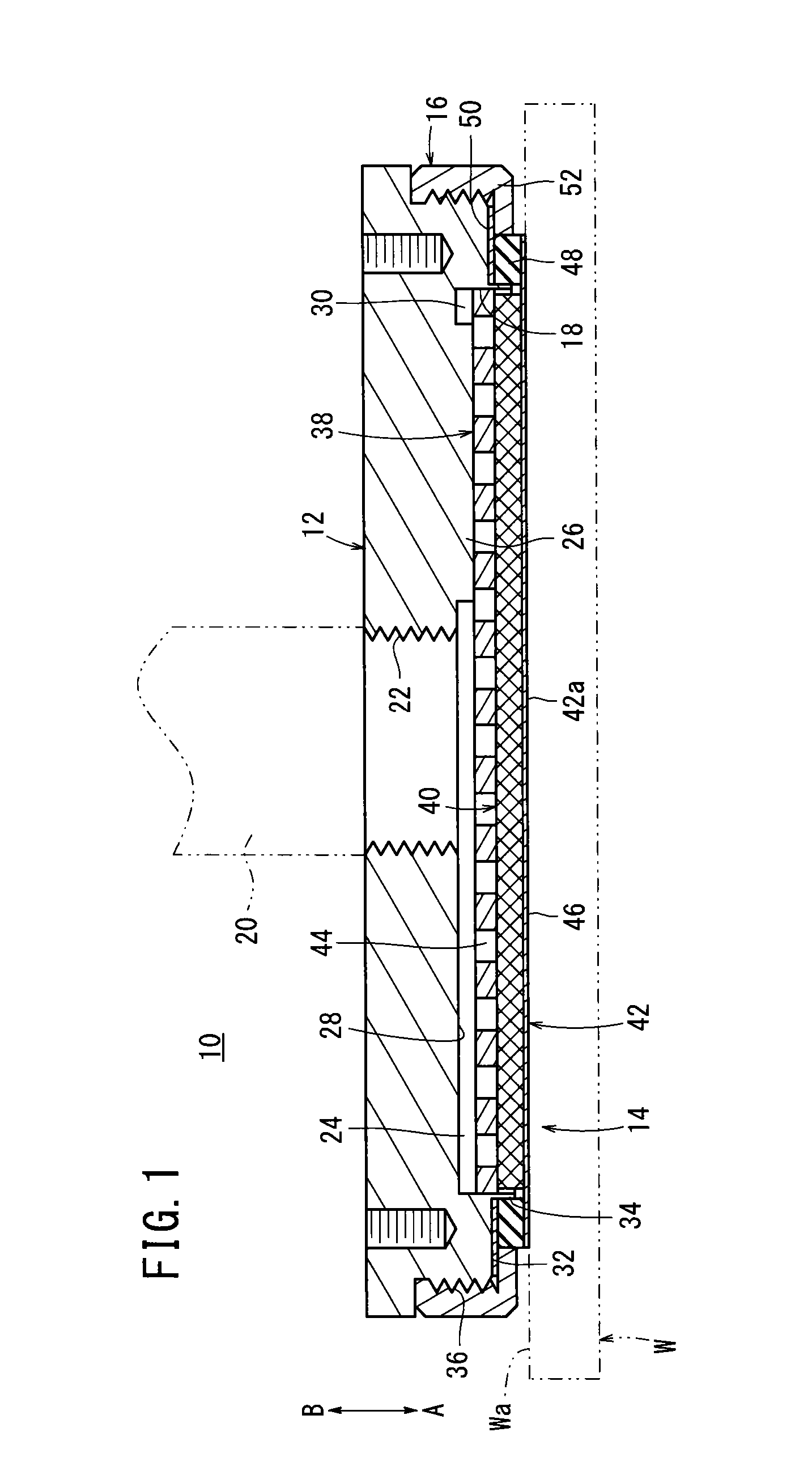
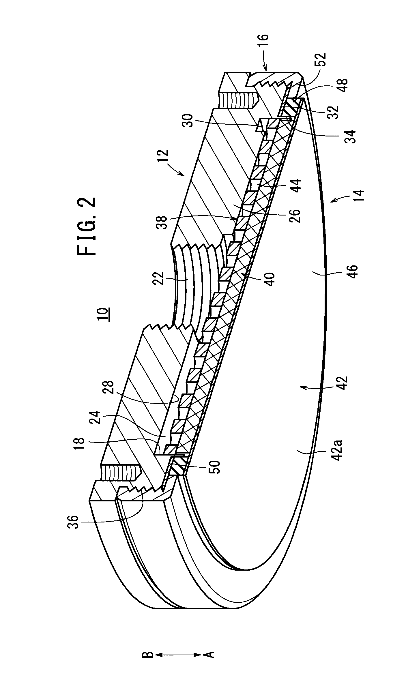
[0019]In FIG. 1, reference numeral 10 indicates a vacuum suction apparatus according to an embodiment of the present invention. As shown in FIGS. 1 through 3, the vacuum suction apparatus 10 includes a body 12 connected to a non-illustrated vacuum generating apparatus, a pad (suction part) 14 disposed on a lower portion of the body 12 and which is capable of attracting a workpiece W under suction, and a ring body (retaining member) 16 that fixes the pad 14 with respect to the body 12. The vacuum suction apparatus 10 is mounted on a distal end of a transport arm or the like of a non-illustrated robot, and through the transport arm, is capable of being moved to a position where the workpiece W is disposed, or to a predetermined position where the workpiece W is to be transported.

[0020]The body 12, for example, is formed in a disk shape from a resin material, and is formed with an opening 18 therein, which opens toward one end surface on the side of the workpiece W (in the direction of...


PUM


Abstract

A vacuum suction apparatus is equipped with a body having a supply port, and a pad provided on a lower portion of the body to which a workpiece can be attracted under suction. The pad is constituted from a base plate accommodated in a space of the body, a flexible intermediate plate provided on a lower portion of the base plate, and a suction sheet body disposed on a lower portion of the intermediate plate and having a sheet that attracts the workpiece under suction. In addition, the base plate, the intermediate plate and the suction sheet body are stacked along an axial direction of the body. The rigidity of the base plate is highest, whereas the rigidities of the intermediate plate and the suction sheet body are lower in this order, and the flexibilities thereof are greater in this order from the base plate.

Description

CROSS-REFERENCE TO RELATED APPLICATION[0001]This application is based upon and claims the benefit of priority from Japanese Patent Application No. 2011-218831 filed on Oct. 3, 2011, of which the contents are incorporated herein by reference.BACKGROUND OF THE INVENTION[0002]1. Field of the Invention[0003]The present invention relates to a vacuum suction apparatus, which is capable of attracting a workpiece under a sucking action of a negative pressure fluid.[0004]2. Description of the Related Art[0005]In recent years, vacuum suction apparatus have been used for transporting sheet or panel shaped workpieces (for example, liquid crystal displays, solar energy cells). Such a vacuum suction apparatus, for example as disclosed in Japanese Laid-Open Patent Publication No. 2004-298970, is equipped with a main body to which a negative pressure or vacuum is supplied to the interior thereof, and a porous body, which is installed via a supporting body to an opening of the main body. A negative ...

Claims


Application Information

Patent Timeline
IPC IPC(8): B25J15/06
CPCB65G47/91Y10S901/40B25B11/007H01L21/6838
Inventor FUKANO, YOSHIHIROSAKURAI, SHUZOSOMEYA, MASAHIKO
Owner SMC CORP
Why Eureka
Try Eureka