Deployment system

a deployment system and slat body technology, applied in the direction of moving aircraft element position indicators, transportation and packaging, aircraft power plants, etc., can solve the problems of slat body jamming, high tensional stress in the slat body, and high stress in the slat attachment and the fixed leading edge, so as to prevent further skewing of the track

Inactive Publication Date: 2013-05-23
AIRBUS OPERATIONS LTD
View PDF17 Cites 19 Cited by
  • Summary
  • Abstract
  • Description
  • Claims
  • Application Information

AI Technical Summary

Benefits of technology

[0009]brake means operable in response to detection of the relative skew by the sensor

Problems solved by technology

Failure in one of the actuators can lead to a jam of the slat deployment mechanism due to the high back driving torque in the actuator.
Such failure can lead to differential track movement causing hi

Method used


Image

  • Deployment system
  • Deployment system
  • Deployment system

Examples


Embodiment Construction

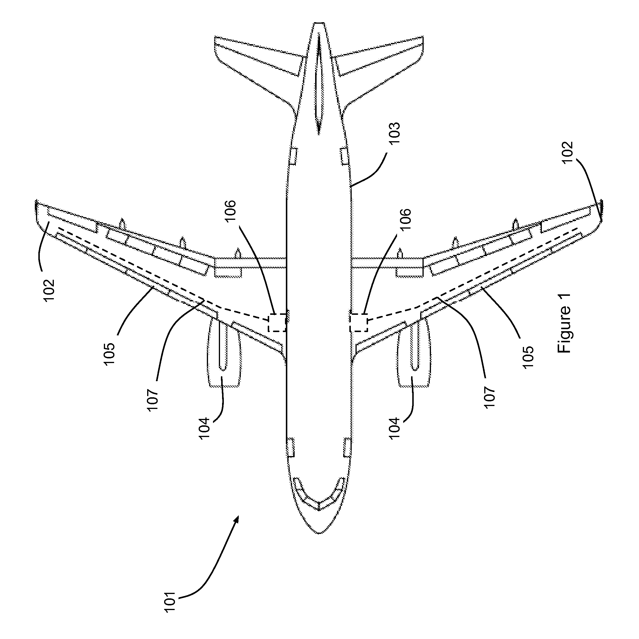
[0021]With reference to FIG. 1, an aircraft 101 comprises a pair of wings 102 faired into a fuselage 103. Each of the wings carries an engine 104. Each of the wings comprises deployable control surfaces in the form of a set of slats 105. Each set of slats 105 is operated by a drive system 106 connected to the slats 105 by a set of torque shafts 107. In the present embodiment, the drive systems 106 each comprises torque limiters (not shown) arranged to limit output force from the drive system 106 to a predetermined level. In the present embodiment, each drive system 106 is operable to shut down in response to the operation or tripping of the associated torque limiter. Such shut down is signalled to the aircraft systems so as to provide an alert to the aircrew.

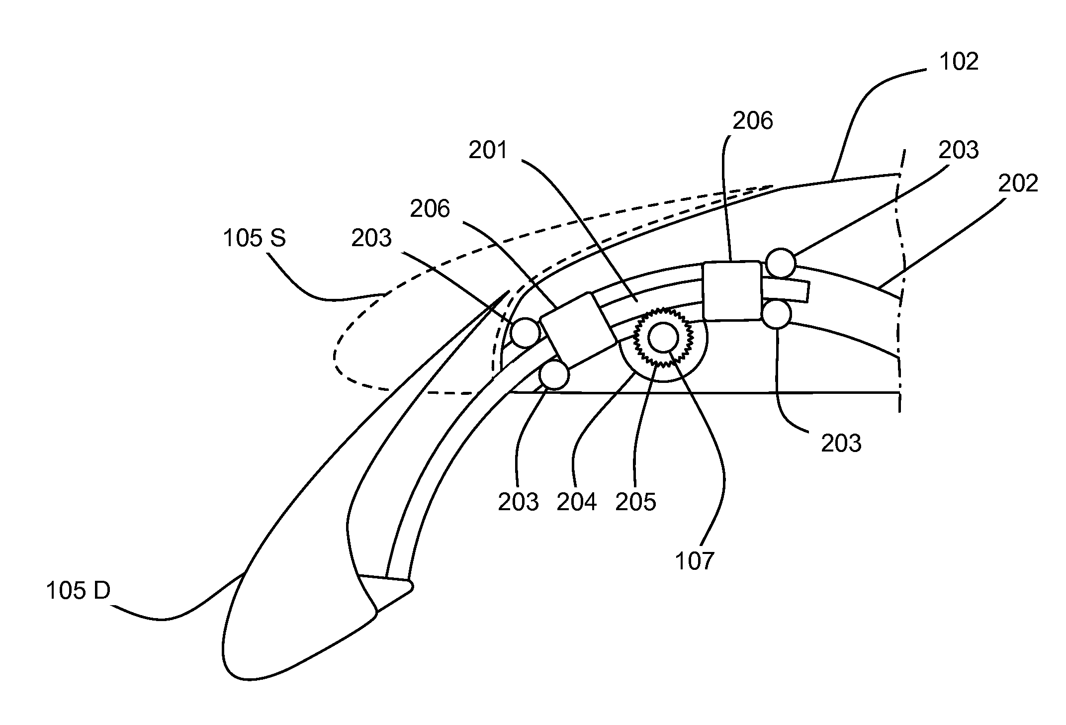
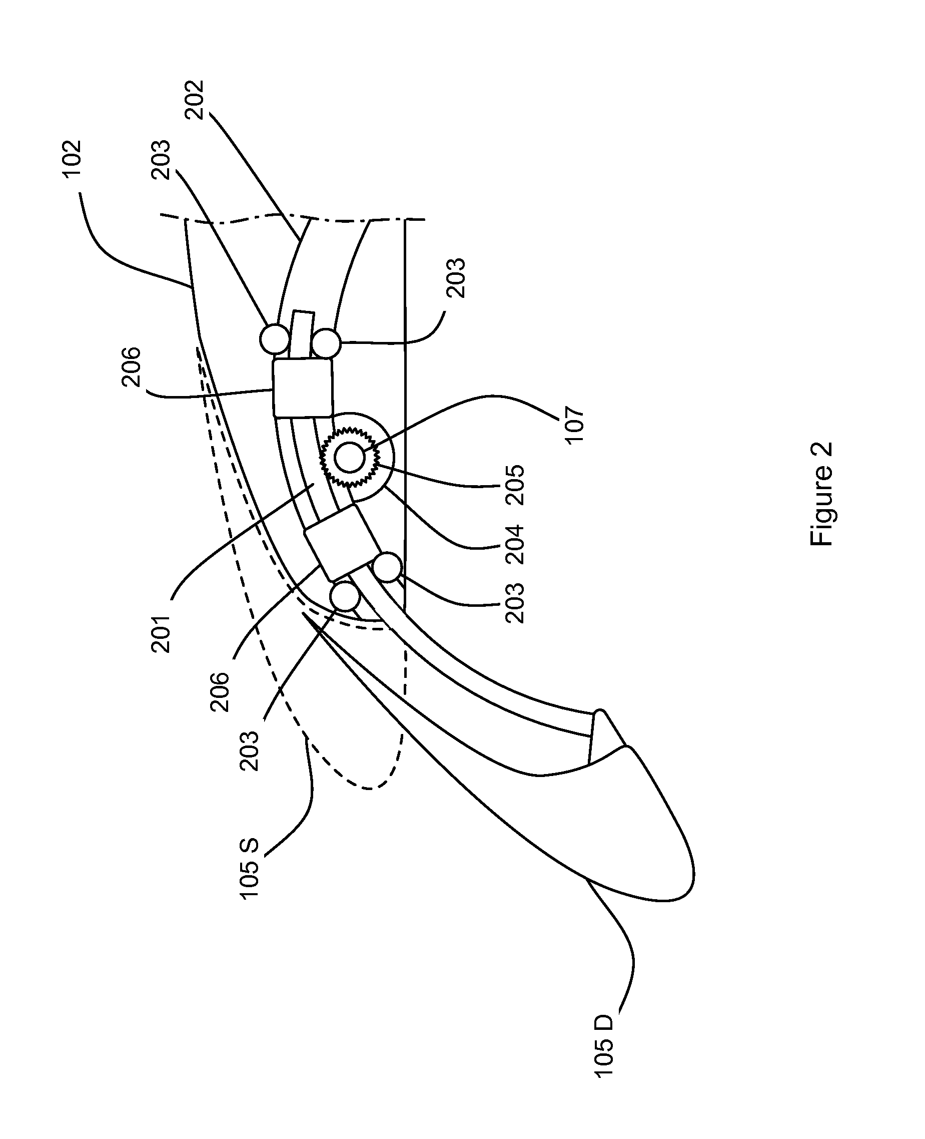
[0022]With reference to FIG. 2, the slats 105 are attached to tracks 201 that are each supported by a support member in the form of a housing 202 fixed to the internal structure of the wing 102. The housing 202 supports a set of...


PUM


Abstract

A deployment mechanism is disclosed for deploying a deployable member supported on tracks relative to a base member and comprising a brake system operable in response to relative skewing of the tracks.

Description

FIELD OF INVENTION[0001]The present invention relates to deployment system for aircraft control surfaces.BACKGROUND OF THE INVENTION[0002]Aircraft wings commonly comprise deployable control surfaces such as slats, droop noses, airbrakes or ailerons. Slats, for example, are commonly supported on the wing fixed leading edge by two tracks driven by actuators arranged to achieve the correct slat to position for take off and landing of the aircraft. Failure in one of the actuators can lead to a jam of the slat deployment mechanism due to the high back driving torque in the actuator. Such failure can lead to differential track movement causing high tensional stresses in the slat body and high stresses in the slat attachment and the fixed leading edge. Such high stress levels increase the possibility of slat detachment from the aircraft wing.SUMMARY OF THE INVENTION[0003]An embodiment of the invention provides a deployment system for deploying a deployable member relative to a base member,...

Claims


Application Information

Patent Timeline
IPC IPC(8): B64C13/28
CPCB64C13/28B64D2045/001B64C9/22B64C9/02
Inventor VAGHELA, NARESH
Owner AIRBUS OPERATIONS LTD
Why Eureka
Try Eureka