Eureka AIR delivers breakthrough ideas for toughest innovation challenges, trusted by R&D personnel around the world.

Vehicle system and vehicle

a vehicle system and vehicle technology, applied in the field of vehicle systems and vehicles, can solve the problems of reduced speed of driver's response to a change in the traffic environment, driver's overconfidence in autonomous driving, and the inability of the driver to respond or feel troublesome to react to a light stimulus

Active Publication Date: 2020-10-13
TOYOTA JIDOSHA KK
View PDF18 Cites 0 Cited by
  • Summary
  • Abstract
  • Description
  • Claims
  • Application Information

AI Technical Summary

Benefits of technology

[0009]According to the above aspect, this vehicle system enables the driver who is aware of driving to pay attention ahead. Moreover, the above aspect allows the vehicle system to give a stimulus also to a non-visual sense of the driver who is not facing forward while a light stimulus is being presented, thus encouraging the driver to face forward. In addition, this vehicle system can give the second warning, which is stronger than the first warning, to a driver whose wakefulness level is further reduced or to a driver who relies on autonomous driving so much that the interest in driving is further reduced. In this way this vehicle system can encourage the driver to pay attention to driving according to the state of the driver.

Problems solved by technology

However, when the wakefulness level of a driver is reduced to some extent or when the driver relies on autonomous driving so much that the driver's interest in driving is reduced, there is a possibility that the driver cannot respond, or feels troublesome to react, to a light stimulus.
The device described in Japanese Unexamined Patent Application Publication No. 2015-138383, if is used for such a driver, does not produce a great effect, sometimes resulting in a reduced speed of driver's response to a change in the traffic environment.
There is a tendency that a driver is overconfident in autonomous driving if the number of times the driver re-holds the steering wheel in response to the second warning is equal to or greater than the threshold.
If a driver does not re-hold the steering wheel in response to the second warning, there is a possibility that wakefulness level of the driver is extremely low.

Method used


Image

  • Vehicle system and vehicle
  • Vehicle system and vehicle
  • Vehicle system and vehicle

Examples


first embodiment

[Outline of Vehicle System 1]

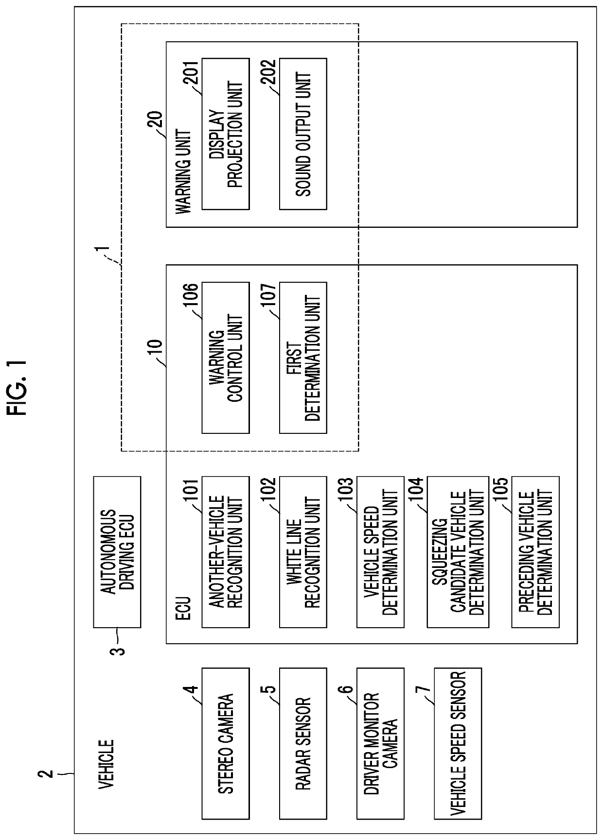
[0042]FIG. 1 is a functional block diagram of a vehicle 2 including a vehicle system 1 according to a first embodiment. The vehicle system 1 is mounted on the vehicle 2 such as a passenger car. The vehicle 2 is a vehicle capable of autonomous driving. Autonomous driving refers to vehicle control in which the vehicle 2 is autonomously driven along a target route that is set in advance. During autonomous driving, the vehicle 2 travels autonomously with no need for the driver to perform the driving operation. The target route is a route on the map on which the vehicle 2 will travel in the autonomous driving mode.

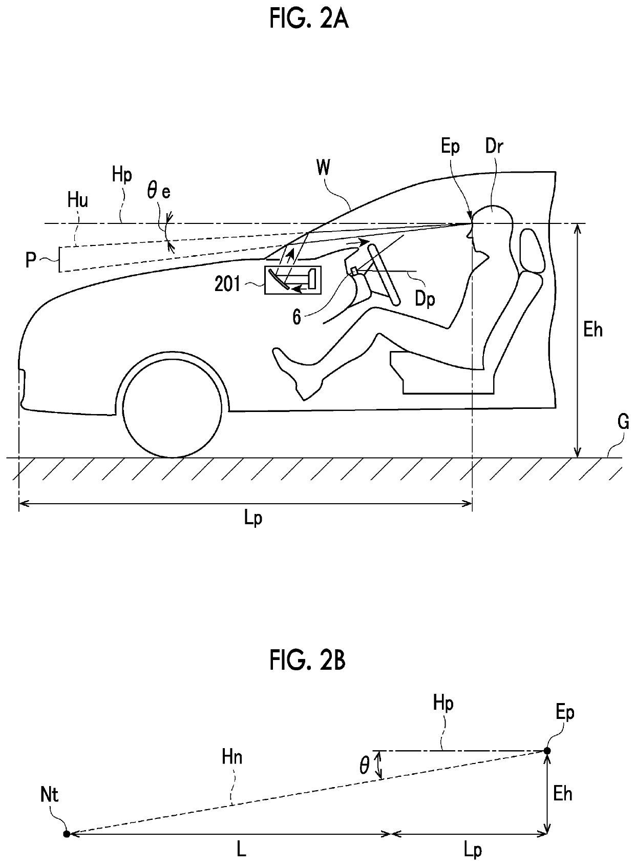
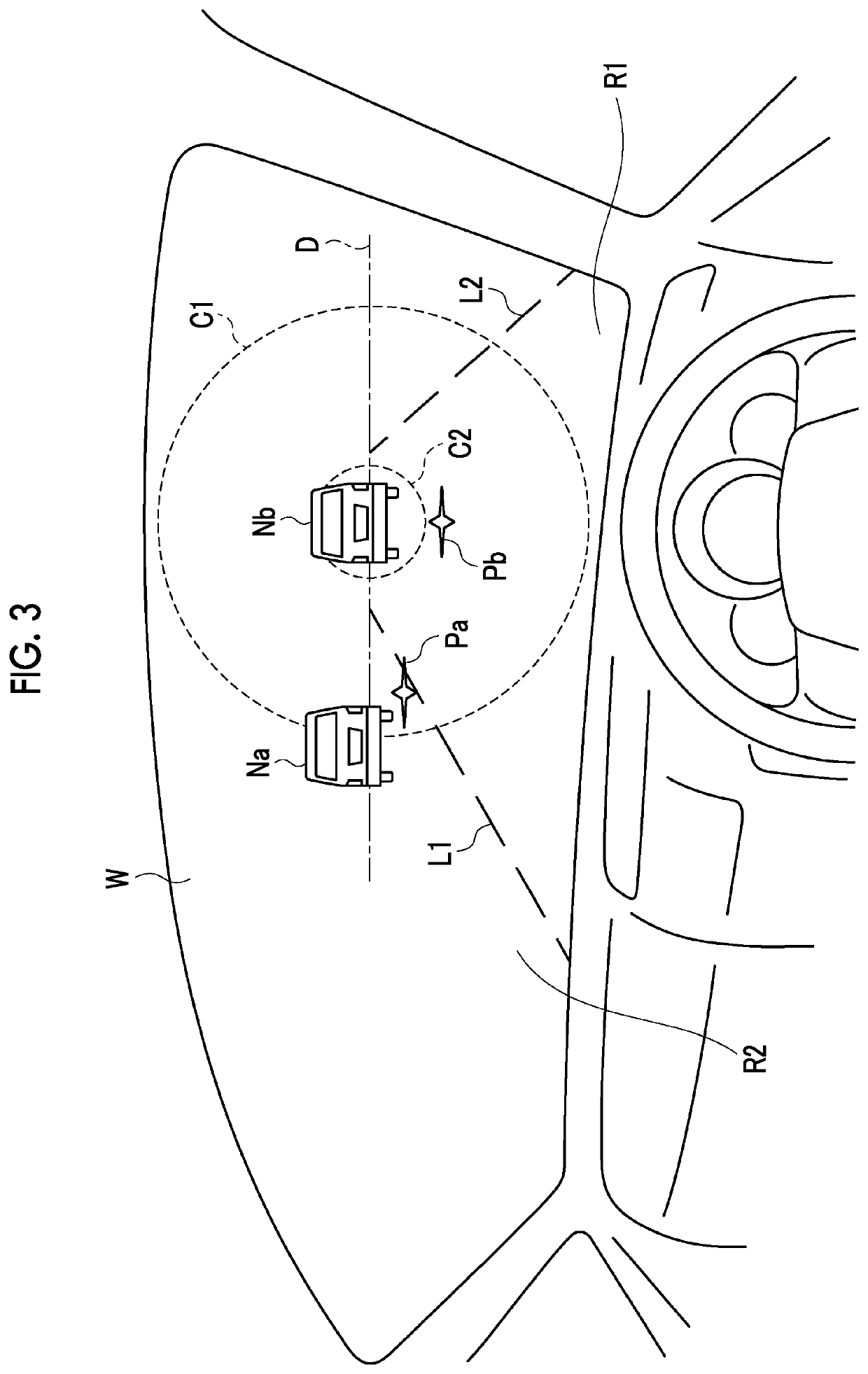
[0043]The vehicle system 1 presents a light stimulus to the driver of the vehicle 2 using the head-up display of the vehicle 2 when a change in the traffic environment is detected ahead of the vehicle 2 during autonomous driving. The traffic environment includes the traveling situation of the vehicles around the vehicle 2, the signal lighting situat...

second embodiment

[0108]A vehicle system 1A according to a second embodiment is different from the vehicle system 1 according to the first embodiment in that a vibration generation unit 203 is provided instead of the sound output unit 202. The other components are the same as those of the first embodiment. In the description of the vehicle system 1A, the description similar to that of the vehicle system 1 is omitted.

[0109]FIG. 10 is a functional block diagram of the vehicle 2 having the vehicle system 1A according to the second embodiment. As shown in FIG. 10, the difference in the configuration between the vehicle system 1A and the vehicle system 1 is that the vehicle system 1A does not include the sound output unit 202 but includes the vibration generation unit 203. The other configuration is the same as that of the vehicle system 1.

[0110]The vibration generation unit 203 is a device that generates a vibration. For example, the vibration generation unit 203 has a weight having a biased center of gr...

third embodiment

[0113]A vehicle system 1B according to a third embodiment is different from the vehicle system 1 according to the first embodiment in that a second determination unit 108 and a vibration generation unit. 203 are provided and in the processing content of a warning control unit 106B. The other components and processing content are the same as those of the first embodiment. In the description of the vehicle system 1B, the description similar to that of the vehicle systems 1 and 1A is omitted.

[0114]FIG. 11 is a functional block diagram of the vehicle 2 having the vehicle system 1B according to the third embodiment. As shown in FIG. 11, the difference in the configuration between the vehicle system 1B and the vehicle system 1 is that the vehicle system 1B includes the warning control unit 106B, the function of which is partially different from that of the warning control unit 106, the second determination unit 108, and the vibration generation unit 203. The other configuration is the sam...


PUM


Abstract

A vehicle system includes a warning device and at least one electronic control unit. The at least one electronic control unit is configured to present a light stimulus to a driver, and determine whether the driver is facing forward, determine whether the driver holds a steering wheel, and cause the warning device to perform a first warning when it is determined that the driver is not facing forward while the light stimulus is being presented. The first warning is either the vibration or the sound. The at least one electronic control unit is configured to perform a second warning when it is determined that the driver does not hold the steering wheel before a predetermined time elapses after the first warning is started. The second warning includes the vibration and the sound.

Description

CROSS-REFERENCE TO RELATED APPLICATIONS[0001]This application claims priority to Japanese Patent Application No. 2016-225084 filed on Nov. 18, 2016, which is incorporated herein by reference in its entirety.BACKGROUND[0002]1. Technical Field[0003]The present disclosure relates to a vehicle system and a vehicle.[0004]2. Description of Related Art[0005]Japanese Patent Application Publication No. 2015-138383 (JP 2015-138383 A) describes a device that includes a head-up display using the windshield in front of a driver. This device blinks the two positions that are spaced equally to the left and to right of the position in front of the driver and are within the driver's peripheral visual range. In this way, the device keeps the driver awake.SUMMARY[0006]However, when the wakefulness level of a driver is reduced to some extent or when the driver relies on autonomous driving so much that the driver's interest in driving is reduced, there is a possibility that the driver cannot respond, or...

Claims


Application Information

Patent Timeline
Patent Type & Authority Patents(United States)
IPC IPC(8): B60W50/14B60W50/16B60W40/08
CPCB60W50/16B60W50/14B60W40/08B60W2040/0827B60W2050/146B60W2050/143B60K2370/334B60K28/06B60K28/066B60R1/00B60T7/12B60R2300/8006
Inventor KIMURA, KENJI
Owner TOYOTA JIDOSHA KK
Why Eureka
Eureka Blog
Learn More