Direct type reflective sheet structure and backlight module

a reflective sheet and backlight technology, applied in the field of display, can solve the problems of color deviation, impose stringent requirements on the ink type or the ratio of phosphors, and the optical quality of the backlight deteriorates,

Active Publication Date: 2020-10-13
HUIZHOU CHINA STAR OPTOELECTRONICS TECHNOLOGY CO LTD
View PDF5 Cites 0 Cited by
  • Summary
  • Abstract
  • Description
  • Claims
  • Application Information

AI Technical Summary

Benefits of technology

[0007]An objective of the present invention is to provide a direct type reflective sheet structure and a backlight module, which can avoid the appearance of color deviation on the display panel and reduce the loss of light.
[0020]With implementing the embodiments of the present invention, the benefits are: in the embodiment of the present invention, by a plurality of triangular prism-shaped microstructures at intervals on the reflective sheet around each of the light emitting diode light sources, each of the microstructures has a reflective surface facing the light emitting diode light sources. The reflective surface can reflect light emitted by the light emitting diode light source through the secondary lens. By controlling the included angle between the reflective surface and the horizontal plane, the light reflected by the reflective sheet can be concentratedly and uniformly reflected to the optical module, so that the problem of color deviation in the prior art can be avoided.
[0021]Moreover, the embodiments of the present invention can avoid the loss of light.

Problems solved by technology

However, in such conventional structure, after adding the phosphor film to the optical module 3′, it is often found that the optical quality of the backlight deteriorates.
The problem of the color deviation due to the use of the phosphor film in such direct type backlight structure may occur in all the direct type phosphor films.
However, this method imposes stringent requirements on the ink type or the ratio of the phosphors.
However, such method also has serious drawbacks.
In case of the film structure with an orthogonal prism, a phosphor film and a reflective polarizer, the target chromaticity of the optical module is difficult to achieve due to insufficient times of the optical path reciprocation at the place where the phosphor film is placed.

Method used


Image

  • Direct type reflective sheet structure and backlight module
  • Direct type reflective sheet structure and backlight module

Examples


Embodiment Construction

[0029]Embodiments of the present invention are described in detail with the technical matters, structural features, achieved objects, and effects with reference to the accompanying drawings as follows. It is clear that the described embodiments are merely part of embodiments of the present invention, but not all embodiments. Based on the embodiments of the present invention; all other embodiments to those of ordinary skill in the premise of no creative efforts obtained, should be considered within the scope of protection of the present invention.

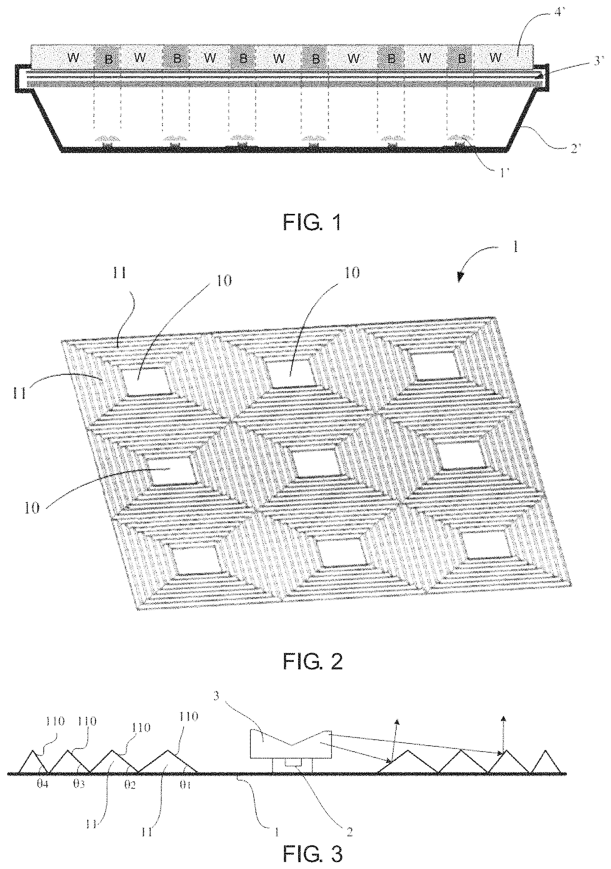
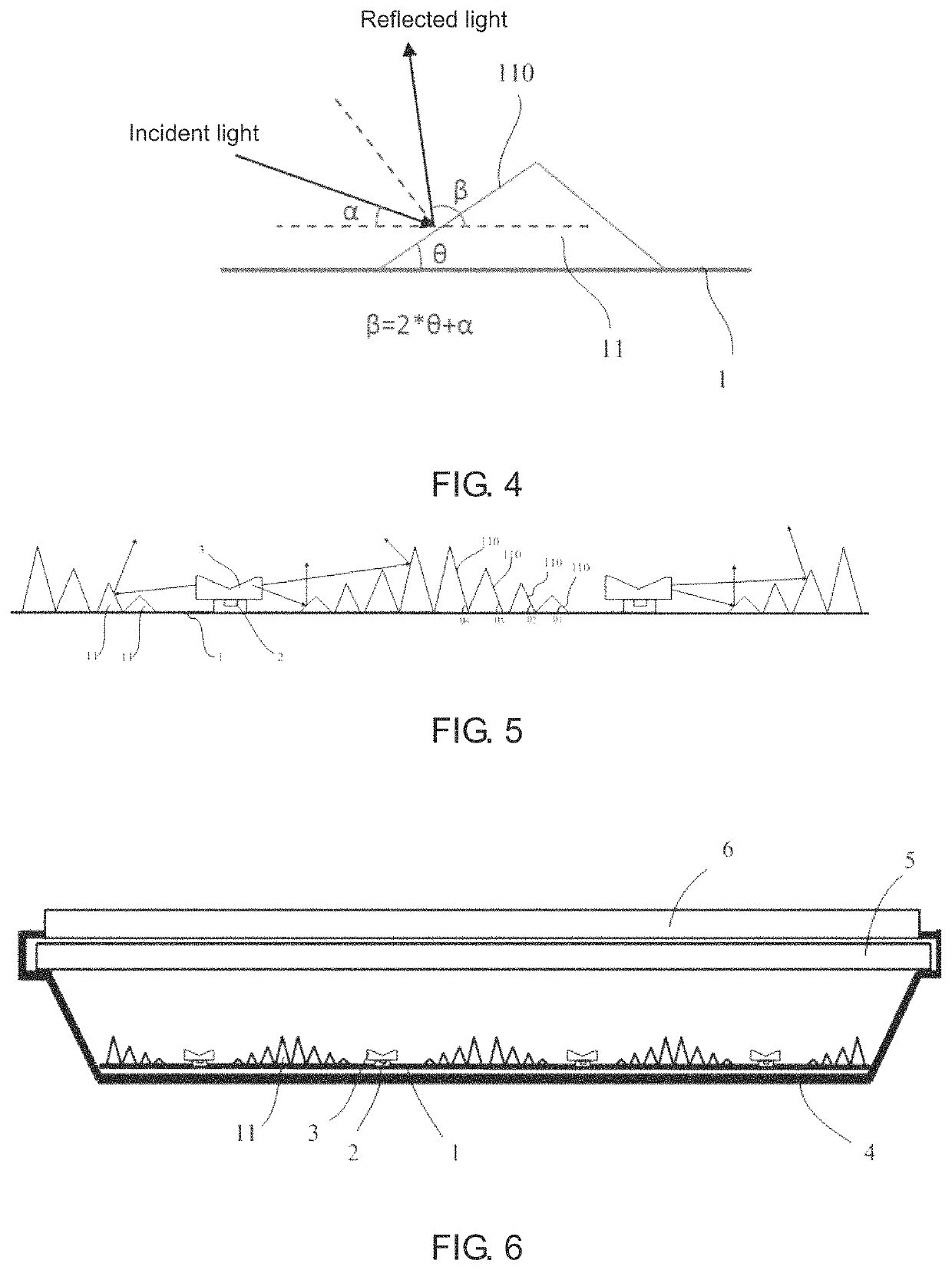
[0030]Please refer to FIG. 2, which illustrates a structural diagram of one embodiment according to a direct type reflective sheet structure provided by the present invention with FIG. 3 and FIG. 4, together. In this embodiment, the direct type reflective sheet structure comprises a reflective sheet 1. A plurality of light emitting diode attaching areas 10 are arranged in an array on the reflective sheet 1. Each of the light emitting diode a...


PUM

PropertyMeasurementUnit
angleaaaaaaaaaa
incidence angleaaaaaaaaaa
included angleaaaaaaaaaa

Abstract

Disclosed is a direct type reflective sheet structure, comprising a reflective sheet, on which a plurality of light emitting diode light sources are arranged in an array. A plurality of triangular prism-shaped microstructures is arranged at intervals on the reflective sheet around each of the light emitting diode light sources. Each of the microstructures has a reflective surface facing the light emitting diode light source to reflect light emitted by the light emitting diode light source. Further disclosed is a direct type backlight module. By implementing the embodiment of the present invention, it can avoid the appearance of color deviation on the display panel and reduce the loss of light.

Description

CROSS REFERENCE[0001]This application is a continuing application of PCT / CN2018 / 078801 filed Mar. 13, 2018, which claims the priority of Chinese Patent Application No. 201810066613.3, entitled “Direct type reflective sheet structure and backlight module”, filed on Jan. 24, 2018, the disclosure of which is incorporated herein by reference in its entirety.FIELD OF THE INVENTION[0002]The present invention relates to a display field, and more particularly to a direct type reflective sheet structure and a backlight module.BACKGROUND OF THE INVENTION[0003]In the prior art, it is commonly used in the liquid crystal display backlight module to add a phosphor film to achieve high saturation display, which is a common means in the market.[0004]As shown in FIG. 1, illustrating a structural diagram of a direct type backlight module in the prior art. It shows that the LED light source 1′ arranged on the backplate 2′ emits light to the optical module 3′ to provide the backlight for the liquid cry...

Claims


Application Information

Patent Timeline
Patent Type & Authority Patents(United States)
IPC IPC(8): F21V7/04F21V8/00G02F1/13357
CPCG02B6/0025G02B6/003G02F1/133603G02B6/0031G02F1/1336G02F1/133602G02F1/133605G02F1/133611
Inventor QIU, YONGYUAN
Owner HUIZHOU CHINA STAR OPTOELECTRONICS TECHNOLOGY CO LTD
Why Eureka
Try Eureka