
Wire harness and power supply device having the same

a technology of power supply device and wire harness, which is applied in the direction of electric/fluid circuit, cable arrangement between relatively moving parts, electric cable installation, etc., can solve the problems of 404/b> being more likely to interfere with the vehicle body and/or appearance deterioration, so as to achieve high flexibility, low flexibility, and high flexibility

Active Publication Date: 2020-10-20
YAZAKI CORP
View PDF35 Cites 2 Cited by
  • Summary
  • Abstract
  • Description
  • Claims
  • Application Information

AI Technical Summary

Benefits of technology

The invention provides a wire harness that has a flexible connecting portion near a sliding door. This allows for a softer connection near the door, which prevents the wire harness from swelling towards the vehicle body during the sliding motion of the door. As a result, the wire harness remains rigid and stable during use.

Problems solved by technology

This is because if the wire harness 404 is swelled to the vehicle body side, then the wire harness 404 is more likely to interfere with the vehicle body and / or appearance is deteriorated.

Method used


Image

  • Wire harness and power supply device having the same
  • Wire harness and power supply device having the same
  • Wire harness and power supply device having the same

Examples


Embodiment Construction

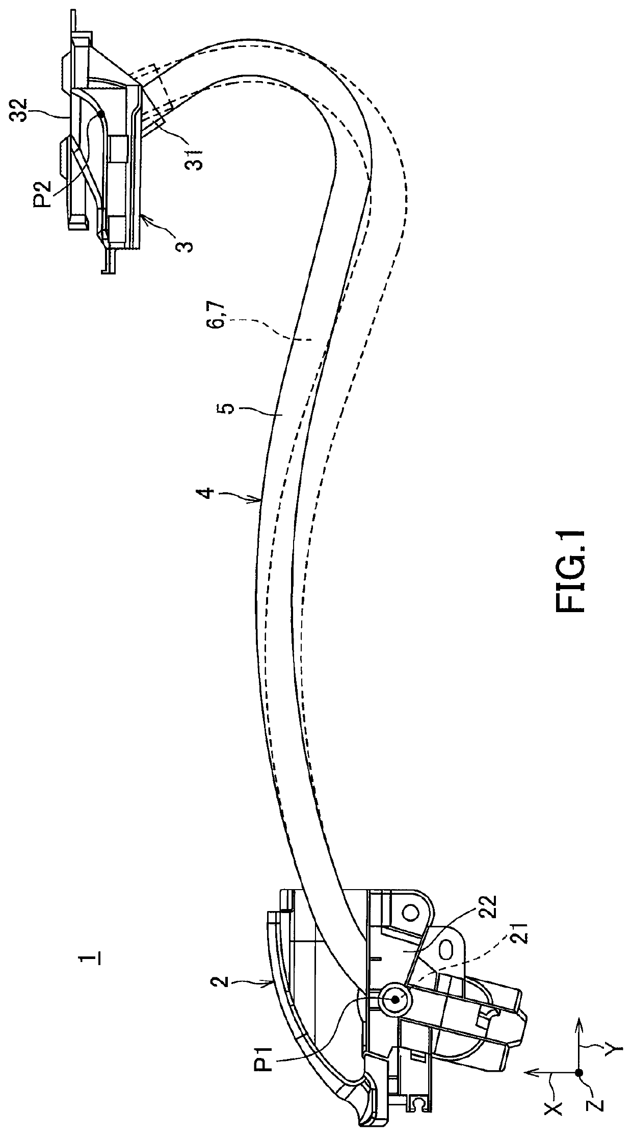
[0018]In the following, “wire harness” and “power supply device” according to one embodiment of the present invention will be explained with reference to FIGS. 1 to 5.

[0019]A power supply device 1 shown in FIG. 1 is configured to be mounted on a motor vehicle and configured to supply power and / or transmit a signal from a vehicle body to an electric component on a sliding door. The power supply device 1 includes a wire harness 4 to be wired from the vehicle body to the sliding door, a body-side unit 2 rotatably supporting an exterior member 5 of the wire harness 4 on the vehicle body side, and a door-side unit 3 rotatably supporting the exterior member 5 on the sliding door side.

[0020]FIG. 1 illustrates a form of the power supply device 1 in the beginning of opening of the sliding door, in which a relative position of the body-side unit 2 and the door-side unit 3 corresponds to a relative position of the body-side unit 402 and the door-side unit 403B of the conventional power supply ...


PUM


Abstract

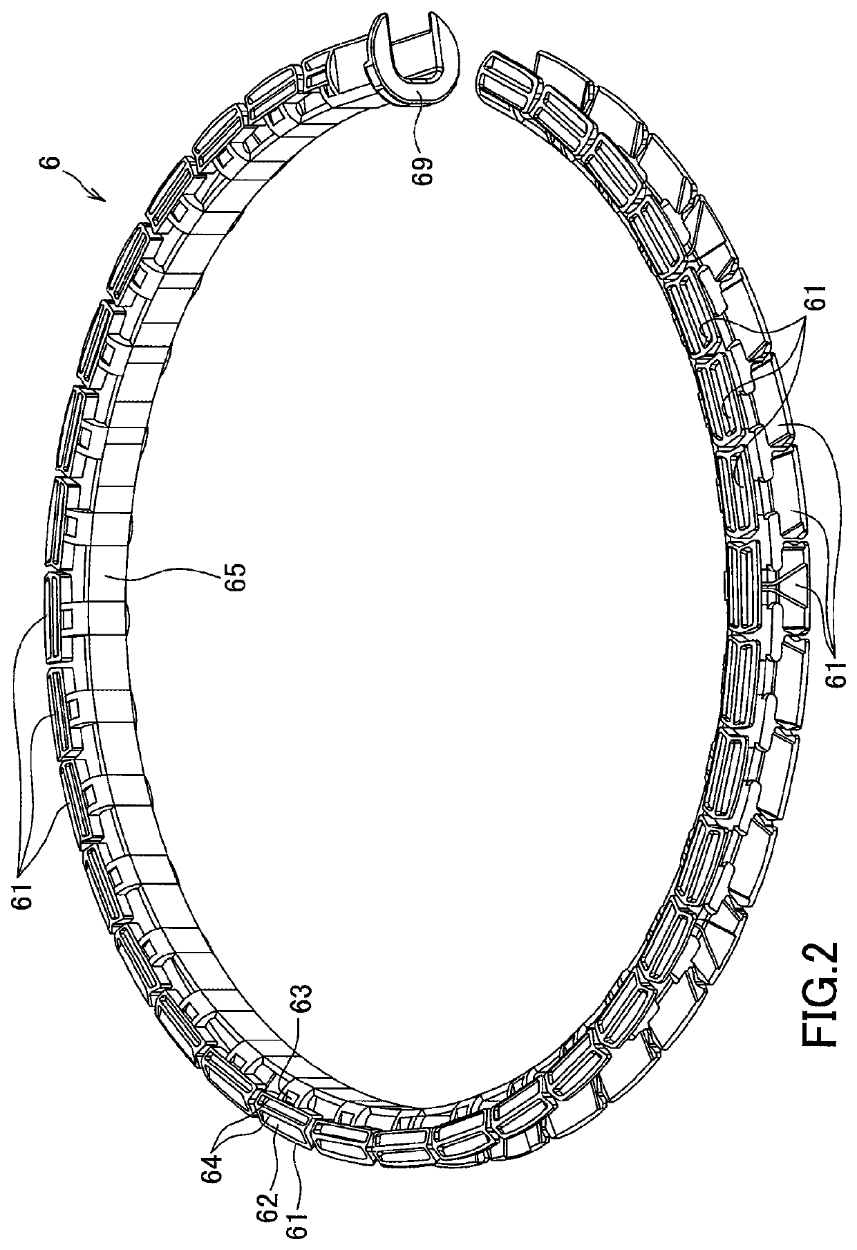
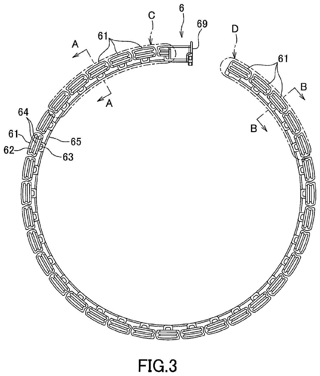
A wire harness includes electric wires, a curvature restricting member and an exterior member. The curvature restricting member includes a strip-like connecting portion and a plurality of pieces and is capable of being curved in orientation that the connecting portion is arranged inside and the pieces are arranged outside. In an inverse orientation, curvature of the curvature restricting member is limited by adjacent pieces abutted onto each other. The curvature restricting member is oriented such that a width direction of the connecting portion is a vertical direction and the connecting portion is positioned outside in a vehicle width direction with respect to the pieces when a sliding door is fully-closed. The connecting portion includes a portion with high flexibility and a portion with low flexibility, and a portion in vicinity of the sliding door has higher flexibility than a portion at a first end side of the curvature restricting member.

Description

TECHNICAL FIELD[0001]The present invention relates to a wire harness mounted on a motor vehicle and configured to supply power and / or transmit a signal from a vehicle body to an electric component on a sliding door.BACKGROUND[0002]Conventionally, a motor vehicle having a sliding door is mounted with a power supply device configured to supply power and / or transmit a signal from a vehicle body to an electric component on the sliding door. FIG. 6 is an illustration illustrating a trajectory of a wire harness of a conventional power supply device (for example, refer to Patent Documents 1 and 2 listed below).[0003]A power supply device 401 shown in FIG. 6 includes a wire harness 404 wired from a vehicle body to a sliding door, a body-side unit 402 and a door-side unit 403. The body-side unit 402 supports a corrugated tube 51 as an exterior member of the wire harness 404 on the vehicle body side such that the corrugated tube 51 is rotatable around an axis line P1. The door-side unit 403 s...

Claims


Application Information

Patent Timeline
Patent Type & Authority Patents(United States)
IPC IPC(8): H02G11/00B60J5/06B60R16/02H02G3/04
CPCB60J5/06B60R16/0207H02G11/00H02G3/0456B60R16/0215B60R16/027
Inventor KATOH, MITSUNOBUYOKOYAMA, MASAKISEKINO, TSUKASA
Owner YAZAKI CORP
Learn More