Arrangement and method for adjusting load in training equipment

a technology for adjusting load and training equipment, which is applied in the direction of sports equipment, muscle exercise devices, weights, etc., can solve the problems of difficult to use outdoor training equipment, difficult to manufacture, install and maintain, and difficult to use. , to achieve the effect of convenient use, simple structure and convenient us

Active Publication Date: 2020-10-27
OMNIGYM OY
View PDF15 Cites 0 Cited by
  • Summary
  • Abstract
  • Description
  • Claims
  • Application Information

AI Technical Summary

Benefits of technology

[0017]The disclosed arrangement for adjusting load in training equipment has a simple structure which makes it straightforward to manufacture, install and maintain once in use. The arrangement and method are easy to utilize. Safety requirements are fulfilled.
[0018]The disclosed arrangement enables adjusting the load of training equipment so that a relatively small change in length of a torque arm causes a significant change in load. This enables efficient and user-specific weight training. Also the dimensions of the training equipment can be kept relatively small, and the equipment can be installed in places where only limited space is available.

Problems solved by technology

This places serious limitations to the load adjustment of the training equipment, and may inhibit users for utilizing pieces of equipment when the fixed load is not suitable for them.
On the other hand, weight plates and other such loose or removable weights are not suited for use in outdoor training equipment.
Apart from storing, changing and maintenance issues, safety issues restrict their use in outdoor training equipment.
Also indoors, these kinds of weights for loading training equipment may cause accidents to the users.
Furthermore, changing loose weights or weight plates is time-consuming and can be even difficult for users with impaired abilities or simply less strength.
The latter naturally limits the utilization of such equipment.

Method used


Image

  • Arrangement and method for adjusting load in training equipment
  • Arrangement and method for adjusting load in training equipment

Examples


Embodiment Construction

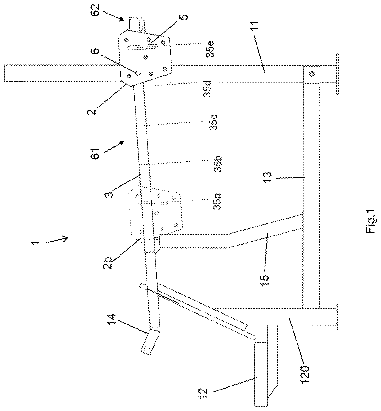
[0026]FIG. 1 presents a piece of training equipment 1, more specifically a front press type strength training unit comprising a seat 12, its foot 120, a frame 11 which in this embodiment is a vertical frame, a lower support frame 13, a moving arm 10 (in FIG. 1 flush behind a guideway 3 and therefore not directly visible), handles 14 arranged onto the moving arm 10 and the guideway 3, a support arm 15 for the moving arm and a load unit 2. The specific frame structure of the different training equipment units naturally depends on the type of exercise for which it is intended.

[0027]Typically, the frame structure 10, 11, 12, 13, 120, 14, 15 of the training equipment is constructed of tubular steel tubes or pipes, bars, beams or similar elongated hollow pieces with either round, square, rectangular or other cross-sections. The pieces may also be solid. Also aluminum, wood or any wood-based material, or engineered composite materials such as plastic composites or any such durable material...


PUM


Abstract

The invention concerns an arrangement for adjusting load in training equipment. The arrangement comprises a load unit, an elongated guideway along which the load unit is arranged to move, a locking device with which the load unit is secured into a position corresponding the desired load of the training equipment, and a connector with which the guideway is pivotally connected to the training equipment via a fulcrum. The guideway is connected both to the moving arm and to a frame of the training equipment via the fulcrum. The invention further concerns a method for adjusting load in training equipment.

Description

CROSS-REFERENCE TO RELATED APPLICATIONS[0001]This application is a national phase entry of International Application No. PCT / FI2016 / 050591, filed Aug. 29, 2016, which claims priority to Finnish Patent Application No. 20155623, filed on Aug. 31, 2015, the entire contents of which are incorporated herein by reference.TECHNICAL FIELD[0002]The present disclosure relates to an arrangement and a method for adjusting load in training equipment. Particularly, the invention relates to adjusting load in training equipment with a monolithic weight, especially in training equipment situated outdoors.BACKGROUND OF THE INVENTION[0003]Load adjustment in training equipment is typically achieved by weight plates or other removable, stackable or otherwise attachable loose, disconnectedly organized weight units. These kinds of solutions are habitually utilized in gyms and other indoor training facilities. In outdoor equipment, there are typically no specific arrangements or methods for load adjustment...

Claims


Application Information

Patent Timeline
Patent Type & Authority Patents(United States)
IPC IPC(8): A63B21/06A63B23/12A63B21/078A63B21/00
CPCA63B21/0616A63B21/0615A63B21/4047A63B21/00069A63B23/1209A63B21/0783A63B21/4043A63B21/08
Inventor HERRANEN, JUHANIKOPONEN, ARIRÄNNÄLÄ, JARI
Owner OMNIGYM OY
Why Eureka
Try Eureka