
Sub-frame mounting structure

a mounting structure and subframe technology, applied in the field of subframe mounting structure, can solve the problems of partial damage to the vehicle body, increase in costs, etc., and achieve the effects of reducing the cost of collision stability of the vehicle, reducing the cost of repair and maintenance of the vehicle, and improving collision stability

Active Publication Date: 2020-10-27
HYUNDAI MOTOR CO LTD +3
View PDF1 Cites 0 Cited by
  • Summary
  • Abstract
  • Description
  • Claims
  • Application Information

AI Technical Summary

Benefits of technology

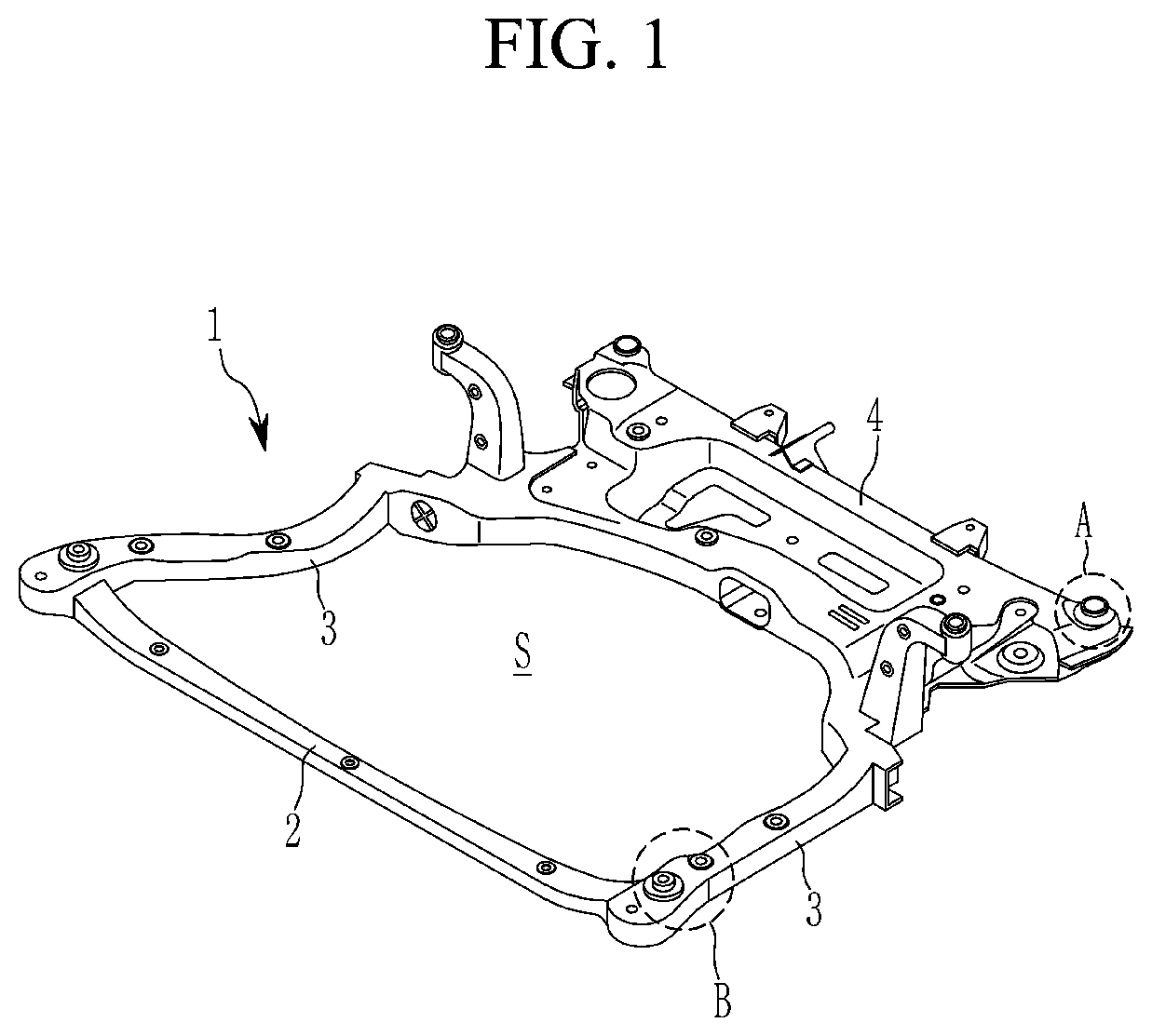
[0006]The present invention provides a sub-frame mounting structure capable of improving collision stability by allowing a sub-frame to be detached from a vehicle body when an impact load of a predetermined size or greater is transferred to a vehicle body portion of the sub-frame, being applied universally regardless of vehicle type, and reducing costs without causing damage to the vehicle body.
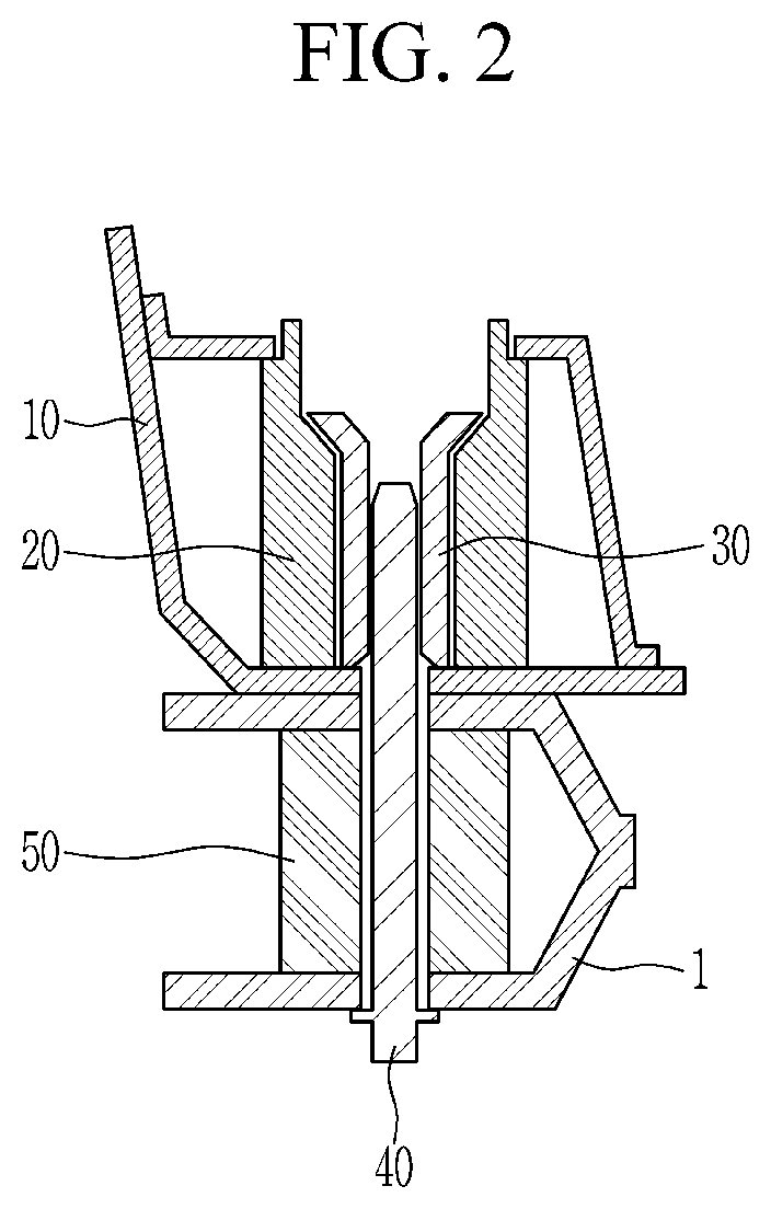
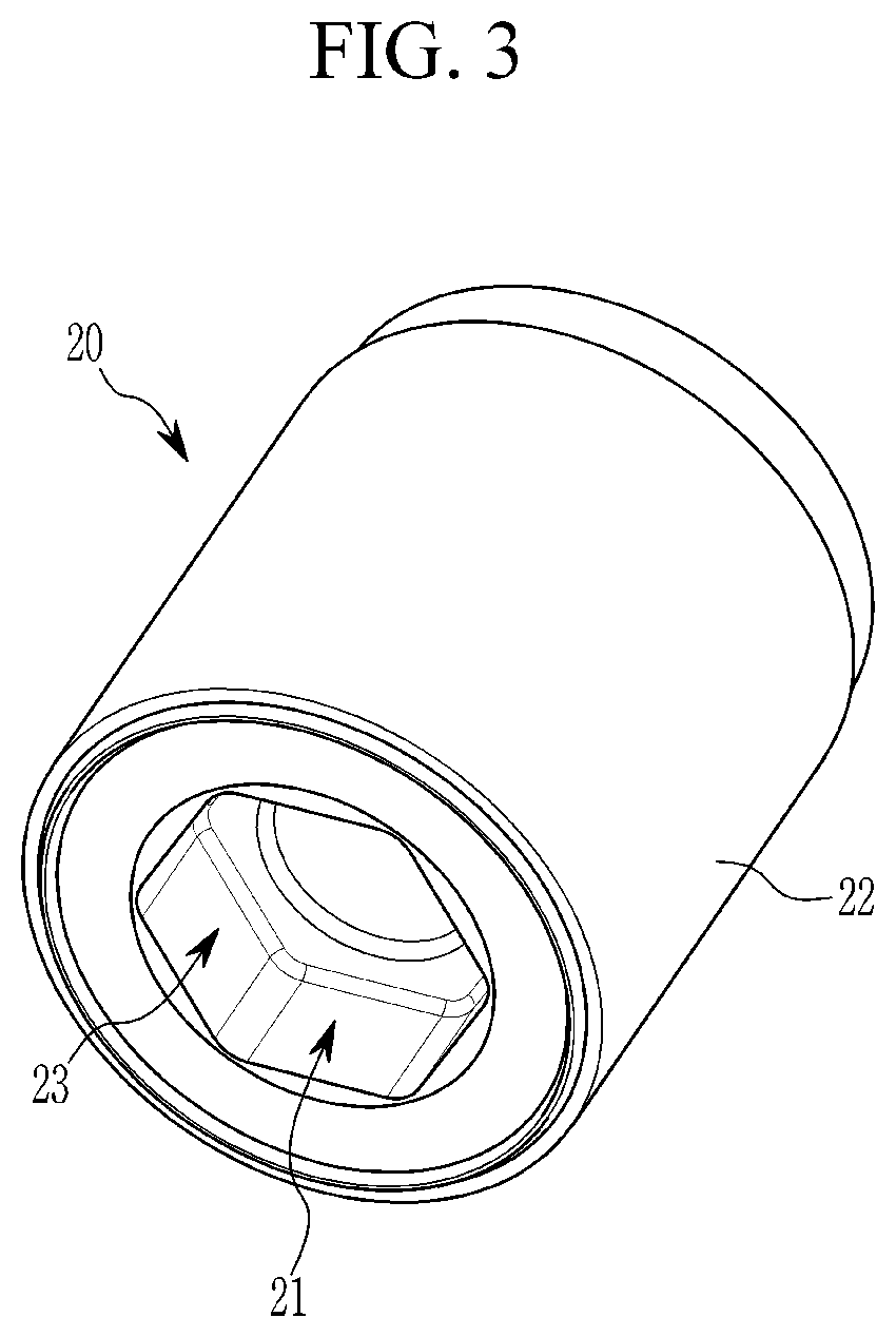
[0012]According to an exemplary embodiment of the present invention, in the sub-frame mounting structure, the outer pipe may be mounted on the vehicle body, and the sub-frame may be mounted on the vehicle body through the inner pipe which is detachably coupled to the outer nut and the mounting bolt fastened to the inner pipe. Therefore, when the impact load of the predetermined load or greater is transferred to the sub-frame, the inner pipe may be detached from the outer pipe to guide a vehicle body detachment of the sub-frame, thereby making it possible to improve collision stability of the vehicle.
[0013]When coupling rigidity of the inner pipe and the outer pipe is properly adjusted, since collision detachment rigidity of the sub-frame may be adjusted, the sub-frame mounting structure may be universally applied to all types of vehicles and the costs thereof may also be reduced. Since the sub-frame does not cause the damage to the vehicle body when being detached from the vehicle body, the repair and maintenance cost of the vehicle may be reduced, and since the sub-frame may be stably supported on the vehicle body, the durability and noise vibration harshness (NVH) performance of the vehicle may be improved.

Problems solved by technology

However, the detachment structure of the bushing or the detachment structure of the sub-frame mounting bolt according to the prior art has disadvantages in that the cost increases and partial damage of the vehicle body occurs.

Method used


Image

  • Sub-frame mounting structure
  • Sub-frame mounting structure
  • Sub-frame mounting structure

Examples


Embodiment Construction

[0023]It is understood that the term “vehicle” or “vehicular” or other similar term as used herein is inclusive of motor vehicles in general such as passenger automobiles including sports utility vehicles (SUV), buses, trucks, various commercial vehicles, watercraft including a variety of boats and ships, aircraft, and the like, and includes hybrid vehicles, electric vehicles, combustion, plug-in hybrid electric vehicles, hydrogen-powered vehicles and other alternative fuel vehicles (e.g. fuels derived from resources other than petroleum).

[0024]The terminology used herein is for the purpose of describing particular embodiments only and is not intended to be limiting of the invention. As used herein, the singular forms “a”, “an” and “the” are intended to include the plural forms as well, unless the context clearly indicates otherwise. It will be further understood that the terms “comprises” and / or “comprising,” when used in this specification, specify the presence of stated features,...


PUM


Abstract

A sub-frame mounting structure is provided. The sub-frame mounting structure includes an outer pipe that is mounted on a vehicle body and an inner pipe that is inserted into and coupled to the outer pipe and detached from the outer pipe when an impact load of a predetermined size or greater is transferred thereto. An anti-rotation structure prevents a relative rotation between the inner pipe and the outer pipe. A sub-frame is fastened to the inner pipe to support the vehicle body through the outer pipe to stably support the vehicle body by the sub-frame and to detach the sub-frame from the vehicle body during a collision.

Description

CROSS-REFERENCE TO RELATED APPLICATION[0001]This application claims priority to and the benefit of Korean Patent Application No. 10-2018-0080849 filed on Jul. 12, 2018, the entire contents of which are incorporated herein by reference.BACKGROUND(a) Field of the Invention[0002]The present invention relates to a sub-frame mounting structure, and more particularly, to a sub-frame mounting structure that allows a sub-frame to be separated from a vehicle body when an impact load of a predetermined size or greater is transferred to the sub-frame.(b) Description of the Related Art[0003]In general, a sub-frame of a vehicle is mounted on a lower portion of a vehicle body, particularly, a lower portion of a side member of the vehicle body to support an engine, a transmission, and the like, and chassis parts are mounted on the sub-frame and supported by the sub-frame. When an impact load is transferred from the vehicle body to the sub-frame during a vehicle collision, the sub-frame is properly...

Claims


Application Information

Patent Timeline
Patent Type & Authority Patents(United States)
IPC IPC(8): B62D27/06B62D29/04B62D21/15
CPCB62D27/06B62D29/04B62D21/155B62D21/11
Inventor RYU, SEHOKIM, YONG KEWSONG, SEA CHEOULKANG, SEUNGMINPARK, SUNG SIKCHOI, SUK HOKIM, TAE HYUNNAM, KI SUNGLEE, MIN JEPARK, SANG EON
Owner HYUNDAI MOTOR CO LTD
Learn More