Overhead transport vehicle

a technology for transporting vehicles and overhead, which is applied in the direction of trolleys, basic electric elements, load-engaging elements, etc., can solve the problems of deteriorating accuracy of transferring articles and tending to roll in the lifting unit, so as to reduce the tilting of the elevator (gripper), stable suspension, and the effect of increasing the safety level

Active Publication Date: 2020-11-03
MURATA MASCH LTD
View PDF10 Cites 0 Cited by
  • Summary
  • Abstract
  • Description
  • Claims
  • Application Information

AI Technical Summary

Benefits of technology

[0004]In view of this, preferred embodiments of the present invention provide overhead transport vehicles that each reduces or prevents swaying of an article while reducing vibrations transmitted to the article.
[0006]In the overhead transport vehicle thus configured, because the base is vertically movable with respect to each of the supports with the vibration-isolators, vibrations generated when the body travels or when the elevator ascends and descends are able to be prevented from being transmitted to the article. Furthermore, in the overhead transport vehicle thus configured, because the link operates so as to ensure similarity of respective distances between the base and the supports in the respective shock absorbers connected to each other, occurrence of rolling motion in the base is reduced or prevented. Thus, tilting of the base is able to be reduced or prevented, and swaying of the article is able to be reduced or prevented. Consequently, it is possible to reduce or prevent swaying of the article while reducing vibrations transmitted to the article.
[0010]In the overhead transport vehicle thus configured, rolling motion in a front-and-rear direction (the direction in which the body unit travels) that occurs, for example, due to acceleration or deceleration during travel is able to be reduced or prevented.
[0012]In the overhead transport vehicle thus configured, rolling motion in the width direction that occurs when, for example, during travel on a curve or when the article is transferred in the lateral direction is able to be reduced or prevented, and also rolling motion in the front-and-rear direction (the direction in which the body unit travels) that occurs, for example, due to acceleration or deceleration during travel is able to be reduced or prevented. Furthermore, it is possible to absorb tilting of the base caused by at least one of change in position of the center of gravity of the article and tolerance thereof in a state in which the article is gripped or in a state in which the article is not gripped, and thus the base is able to be kept level.
[0014]In the overhead transport vehicle thus configured, the elevator is suspended by the four suspensions, but is in a state of being suspended substantially at three locations by two joints between the elevator and two suspensions that are not attached to the swing and one swing that is swingably connected in the elevator. Thus, an effect similar to that in the case of being suspended by three suspensions is able to be obtained, such that the elevator is more stably suspended. Furthermore, even if one suspension has been cut for some reason, the suspended state is able to be maintained, and thus the safety level is able to be increased more than in the case of being actually suspended by three suspensions.
[0015]According to an aspect of a preferred embodiment of the present invention, it is possible to reduce tilting of the elevator (gripper) while reducing vibrations transmitted to the article.

Problems solved by technology

However, for example, rolling motion tends to occur in the lifting unit due to acceleration during travel or centrifugal force during travel on a curve.
The rolling motion thus occurring tilts the lifting unit thereby causing the article to sway, and causes the problem that, for example, the article is brought into contact with a cover of the overhead transport vehicle or accuracy of transferring the article deteriorates.

Method used


Image

  • Overhead transport vehicle
  • Overhead transport vehicle
  • Overhead transport vehicle

Examples


Embodiment Construction

[0024]Preferred embodiments of the present invention will now be described in detail with reference to the drawings. In the description of the drawings, like elements are designated by like reference signs, and duplicated explanation is omitted.

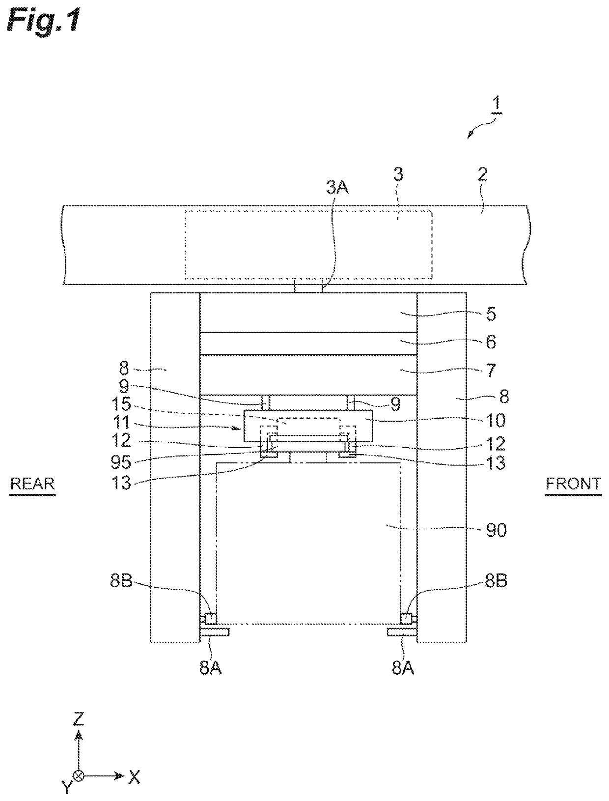
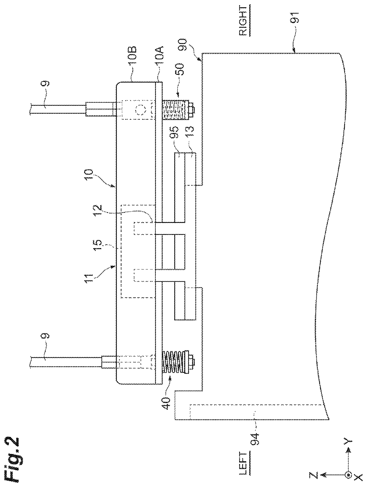
[0025]FIG. 1 is a front view illustrating an overhead transport vehicle according to the present preferred embodiment, and FIG. 2 is a side view of the overhead transport vehicle in FIG. 1 when viewed from front. In FIG. 1 and FIG. 2, illustration of a link mechanism 70 is omitted. This overhead transport vehicle 1 depicted in FIG. 1 travels along a traveling rail 2 provided at a position higher than a floor, e.g., at a ceiling of a clean room. The overhead transport vehicle 1 conveys a front opening unified pod (FOUP) (article) 90 as an article between a storage facility and a predetermined load port, for example. The FOUP 90 accommodates a plurality of semiconductor wafers, reticles, or the like. The FOUP 90 includes a flange 95 to be held ...


PUM


Abstract

In an overhead transport vehicle, an elevator includes shock absorbers attached to belts, and a base including a holder. The shock absorbers each include a support below the base. The base is vertically movable with respect to each of the supports with vibration isolators. The shock absorbers are connected by a link that operates to ensure similarity of respective distances between the base and the support connected to each other in each of the shock absorbers.

Description

BACKGROUND OF THE INVENTION1. Field of the Invention[0001]One aspect of the present invention relates to an overhead transport vehicle.2. Description of the Related Art[0002]An overhead transport vehicle includes a body unit configured to travel along a track, and a lifting unit including a gripping unit configured to grip an article, the lifting unit configured to ascend and descend with respect to the body unit by winding and paying out a plurality of suspending members is known. For example, Japanese Unexamined Patent Publication No. 2016-94263 discloses an overhead transport vehicle in which shock-absorbing elements that are elastically deformable in the vertical direction are disposed between a lifting unit and a gripping unit. With the overhead transport vehicle thus configured, vibrations generated when a traveling body travels or when the lifting unit ascends and descends can be prevented from being transmitted to an article.[0003]In the conventional overhead transport vehic...

Claims


Application Information

Patent Timeline
Patent Type & Authority Patents(United States)
IPC IPC(8): B66C13/06B65G1/04B66C11/00B66C19/00H01L21/677
CPCH01L21/67733B66C19/00H01L21/67706H01L21/67724B65G1/04B66C13/06B66C11/00H01L21/67712H01L21/67751B65G1/0457B65G2201/0297
Inventor KOBAYASHI, MAKOTO
Owner MURATA MASCH LTD
Why Eureka
Try Eureka