
Voltage dividing resistor

a resistor and voltage division technology, applied in the direction of resistors, resistor details, electrical equipment, etc., can solve the problem of becoming less applicabl

Active Publication Date: 2020-11-03
CHROMA ATE
View PDF9 Cites 0 Cited by
  • Summary
  • Abstract
  • Description
  • Claims
  • Application Information

AI Technical Summary

Benefits of technology

This solution enables the generation of adequate voltage signals with reduced space requirements, providing more options for engineers and preventing inconsistent resistance values due to heat dissipation, thus facilitating circuit miniaturization and improved performance.

Problems solved by technology

As is common practice, dividing or reducing a larger voltage from a power source may give the requisite voltage signal, albeit often a low-definition one beset by noise.
Said practice involves the employment of intricate electronic elements or resistors covering a large area, and is becoming less applicable due to shrinking circuit dimensions.

Method used


Image

  • Voltage dividing resistor
  • Voltage dividing resistor
  • Voltage dividing resistor

Examples


Embodiment Construction

"d_n">[0015]The features, objections, and functions of the present invention are further disclosed below. However, it is only a few of the possible embodiments of the present invention, and the scope of the present invention is not limited thereto; that is, the equivalent changes and modifications done in accordance with the claims of the present invention will remain the subject of the present invention. Without departing from the spirit and scope of the invention, it should be considered as further enablement of the invention.

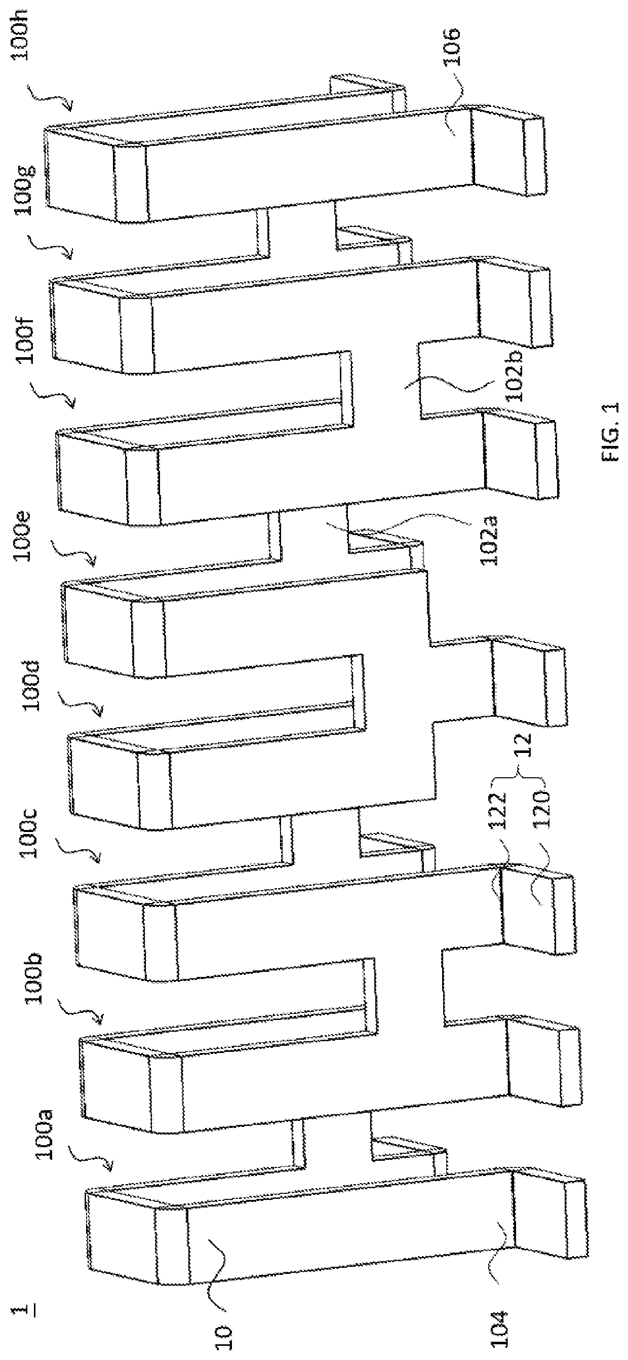
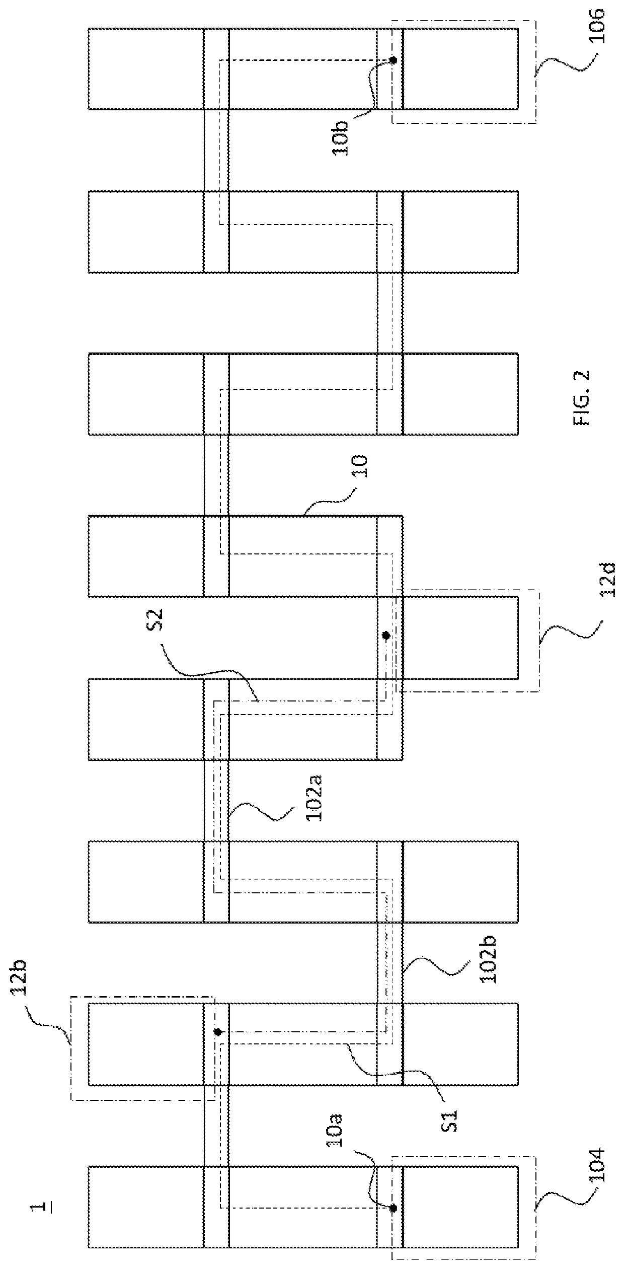
[0016]Please refer to FIGS. 1 and 2 in conjunction. According to an embodiment of the present invention, FIG. 1 is a stereogram of a voltage dividing resistor 1, and FIG. 2 a bird's-eye view of the same. As depicted in the figures, the voltage dividing resistor 1 comprises a resistance bar 10 and a plurality of dividing connectors 12. The dividing connectors 12 are connected to different locations of the resistance bar 10. The resistance bar 10 and the dividi...


PUM


Abstract

Herein disclosed is a voltage dividing resistor comprising a resistance bar and a plurality of dividing connectors. The resistance bar has a first end and a second end and provides a first current path, which stretches from the first end to the second end along the resistance bar. The distance between the first end and the second end is less than the length of the first current path. The first and second ends are configured to be electrically connected to a power source. The dividing connectors are electrically connected to different locations on the first current path. Each of the dividing connectors has a contact pad. The resistance bar is not coplanar with the contact pads. A divided voltage is obtained from a pair of dividing connectors chosen from the plurality of dividing connectors.

Description

CROSS REFERENCE TO RELATED APPLICATION[0001]The present application claims priority to Taiwan patent application Serial No. 107142017 filed on Nov. 26, 2018, the entire content of which is incorporated by reference to this application.BACKGROUND OF THE INVENTION1. Field of the Invention[0002]The present invention pertains to a resistor, in particular one that has a plurality of contact pads. Selecting different contact pads of the resistor yields a variety of resistance values.2. Description of the Prior Art[0003]To perform adequate tests on electronic devices of different model numbers and therefore non-identical specifications, engineers adjust settings on their test instruments first. The output voltage signal of a test instrument, for instance, has to fall within a certain range for an electronic device to be able to read. As is common practice, dividing or reducing a larger voltage from a power source may give the requisite voltage signal, albeit often a low-definition one bese...

Claims


Application Information

Patent Timeline
Patent Type & Authority Patents(United States)
IPC IPC(8): H01C1/14H01C1/084
CPCH01C1/14H01C1/084H01C3/08H01C10/06H01C10/08
Inventor LIU, CHUNG-LINHUANG, CHIEN-HSINCHEN, WEN-CHUNG
Owner CHROMA ATE
Learn More