Swivels

a technology of swivels and swivels, which is applied in the direction of swivels, load-engaging elements, ropes and cables for vehicles/pulleys, etc., can solve the problem of not having a current solution available to limit rotation to a predefined angl

Active Publication Date: 2020-11-17
TREEMAGINEERS
View PDF12 Cites 2 Cited by
  • Summary
  • Abstract
  • Description
  • Claims
  • Application Information

AI Technical Summary

Benefits of technology

[0004]An aim of this invention is to provide a connecting component that can operate as a conventional swivel, can allow limited rotation, and / or prevent rotation altogether, and which allows a user to easily select the required mode of operation.
[0011]When using a swivel embodying the invention, it is possible for the user to select whether the swivel should allow free rotational movement between components to which it is connected or should restrict such rotational movement simply by operating the user control. This avoids the necessity of dismantling and re-assembling a climbing or rigging system in order to achieve that change of function.
[0012]Alternatively or additionally, in the rotation limiting arrangement, in the second locking condition, typically, the limited mutual rotation is in excess of 90°. More typically, the limited mutual rotation may be in excess of 200° or 220°. There are further possible alternative arrangements. For example, the second rotation limiting arrangement may allow mutual rotation of the first and the second body components in a plurality of separate rotational ranges. Alternatively or additionally, the limiting arrangement, in the first locking condition, may substantially prevent mutual rotation of the first and the second body components at one of several mutual rotational positions. In some embodiments, the rotation limiting arrangement can be assembled in a plurality of configurations to enable the position of mutual rotation at which rotation is limited to be adjusted.

Problems solved by technology

At present, this would require the user to uncouple themselves from their system to remove the swivel to stop rotation or attach to a fixed object, and there is no current solution available to limit rotation to a predefined angle.

Method used


Image

  • Swivels
  • Swivels
  • Swivels

Examples


Embodiment Construction

[0030]Embodiments of the invention will now be described in detail, by way of example, and with reference to the accompanying drawings.

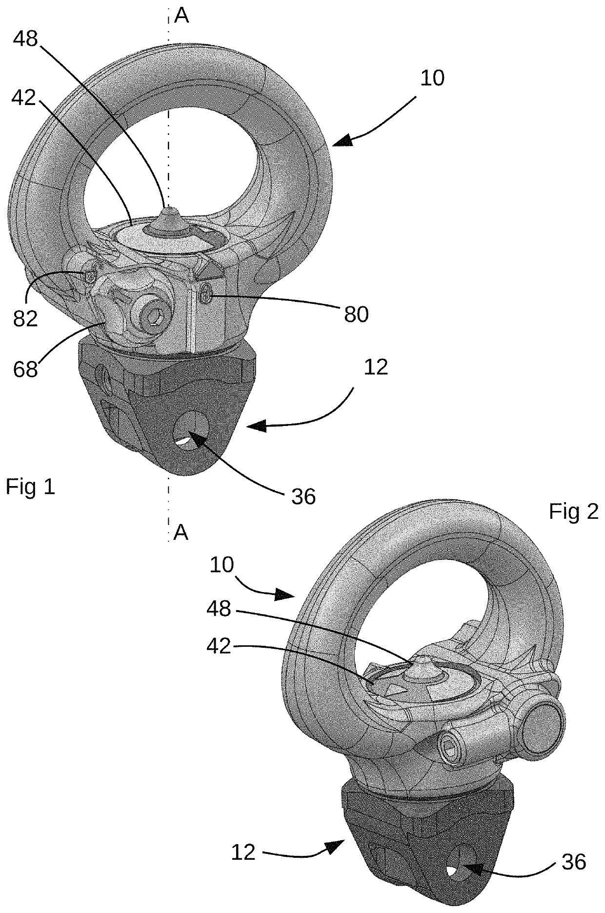
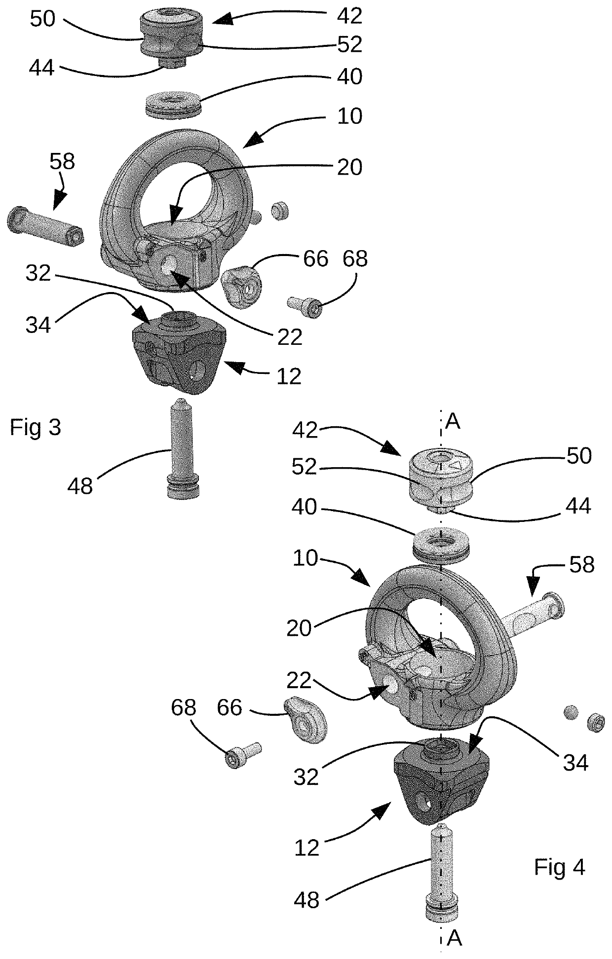
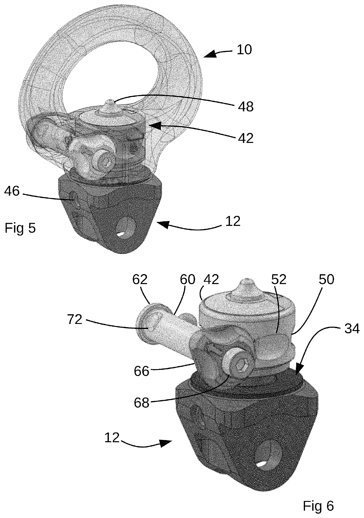
[0031]With reference to FIGS. 1 and 2, a swivel embodying the invention comprises an eye 10 being a first body component and a boss 12 being a second body component. This configuration of swivel can be used to interconnect a rigid component 14 (shown in FIG. 7) to which the boss 12 is attached, and a flexible component, such as a rope or webbing or a carabiner to which the eye 10 is attached.

[0032]The eye 10, a unitary metal component, comprises a loop that extends from a connection region. In the connection region, the eye 10 includes a bearing chamber 20 that is a cylindrical void centred on a swivel axis A of the swivel and opening in a direction facing away from the boss 12. The eye 10 has a flat, annular bearing surface that faces towards the boss 12 and extends in a plane normal to the axis A. A circular aperture extends through the bearing sur...


PUM


Abstract

A swivel comprises a first body component and a second body component with an interconnection assembly for interconnecting the first and second body components and to allow mutual rotation of the first and second components about a swivel axis. The swivel further includes a rotation limiting arrangement which, in a release condition, allows free mutual rotation of the first and second body components and in a first or a second locking condition restricts mutual rotation of the first and second body components. A user control is operable to selectively cause the rotation limiting arrangement to adopt one of a locking condition and the release condition. In the first locking condition, the rotation limiting arrangement prevents mutual rotation of the first and the second body components and in the second locking condition, the rotation limiting arrangement, allows limited mutual rotation of the first and second body components by less than 360°.

Description

BACKGROUND TO THE INVENTIONField of the Invention[0001]This invention relates to swivels.[0002]A swivel is an anti-torsion device for reducing the twisting loads within climbing and lifting systems. Traditionally, these have constituted of an assembly that includes pair of swivel bodies with a thrust or roller bearing joining the two bosses to enable them to spin independently. Without a swivel, torsional forces could cause damage or failure to other parts of a climbing or rigging system by applying a too high torsional loading, or alternatively could allow a mass to spin uncontrollably. Existing swivels are intended to provide a 360° rotation action and are able to rotate clockwise or anti-clockwise for an indefinite number of rotations.SUMMARY OF THE INVENTION[0003]The present inventors have realised that in some applications in which a user might require a connection between components in which in one instance allows 360° rotation (as with a conventional swivel), in another insta...

Claims


Application Information

Patent Timeline
Patent Type & Authority Patents(United States)
IPC IPC(8): F16C11/10F16G15/08B66C1/66
CPCF16C11/10B66C1/66F16G15/08F16G11/00
Inventor COWELL, CHRISTOPHER SIDNEYTANNER, ELLIOT JAMES
Owner TREEMAGINEERS
Why Eureka
Try Eureka