
Parallel and square alignment tool

a technology alignment parts, applied in the field of parallel and square alignment tools, can solve the problems of requiring more time for marking or layout of the operation to be performed, and achieve the effects of improving efficiency and accuracy, simple and effective connection to work components, and resisting unintended changes during us

Active Publication Date: 2020-11-24
TSO PROD LLC
View PDF41 Cites 6 Cited by
  • Summary
  • Abstract
  • Description
  • Claims
  • Application Information

AI Technical Summary

Benefits of technology

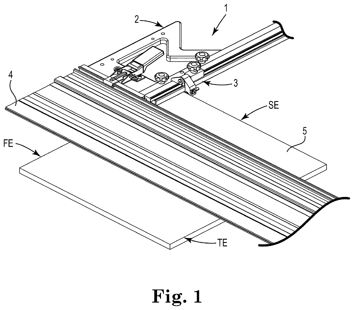
[0006]The purpose and advantages of the present invention will be set forth in and apparent from the description and drawings that follow, as well as will be learned by practice of the claimed subject matter. It is the object of this invention to introduce a parallel and square alignment tool and method of using the alignment tool that effectively provide a connection to a work component which is precise, as well as simple, and resistant to unintended change during use. The present invention improves efficiency and accuracy when making a cut that is perpendicular to a first edge of the work piece while being parallel to a second edge of the work piece, by permitting accurate placement of the work component relative to the work piece in one layout step.
[0008]The disclosed parallel and square alignment tools simplify and speed up set up for repeatable perpendicular and parallel cuts or routing operations, while reducing the potential for dimensional variations when cutting or routing flat sheet materials to common square or rectangular shapes. In the construction of objects like cabinets, it is more critical that the components are identical than a particular precise dimension. In performing operations with portable power or hand tools, frequently the marking or layout of the operation to be performed requires more time than the actual operation using a power tool. Computer Numerical Controlled machine tools have solved this problem for industrial production. The present invention brings the handheld power tool user closer to the repeatable accuracy and speed of industrial operations, while enhancing the convenience and confidence during cutting and routing operations.

Problems solved by technology

However, unlike the prior art, the inventive alignment tools do not rely on multiple separate steps to achieve alignment when bringing the work component to first and successive work pieces, and avoid the aforementioned disadvantages of such traditional connections.
In performing operations with portable power or hand tools, frequently the marking or layout of the operation to be performed requires more time than the actual operation using a power tool.

Method used


Image

  • Parallel and square alignment tool
  • Parallel and square alignment tool
  • Parallel and square alignment tool

Examples


Embodiment Construction

[0020]For the following defined terms, these definitions shall be applied, unless a different definition is given in the claims or elsewhere in this disclosure. As used in this disclosure and the claims, the singular forms “a”, “an”, and “the” include plural referents unless the content clearly dictates otherwise. As used in this disclosure and the claims, the term “or” is generally employed in its sense including “and / or” unless the content clearly dictates otherwise.

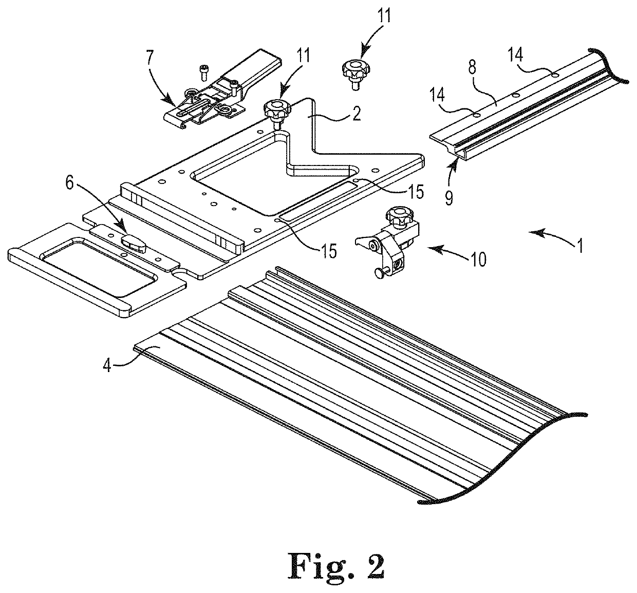
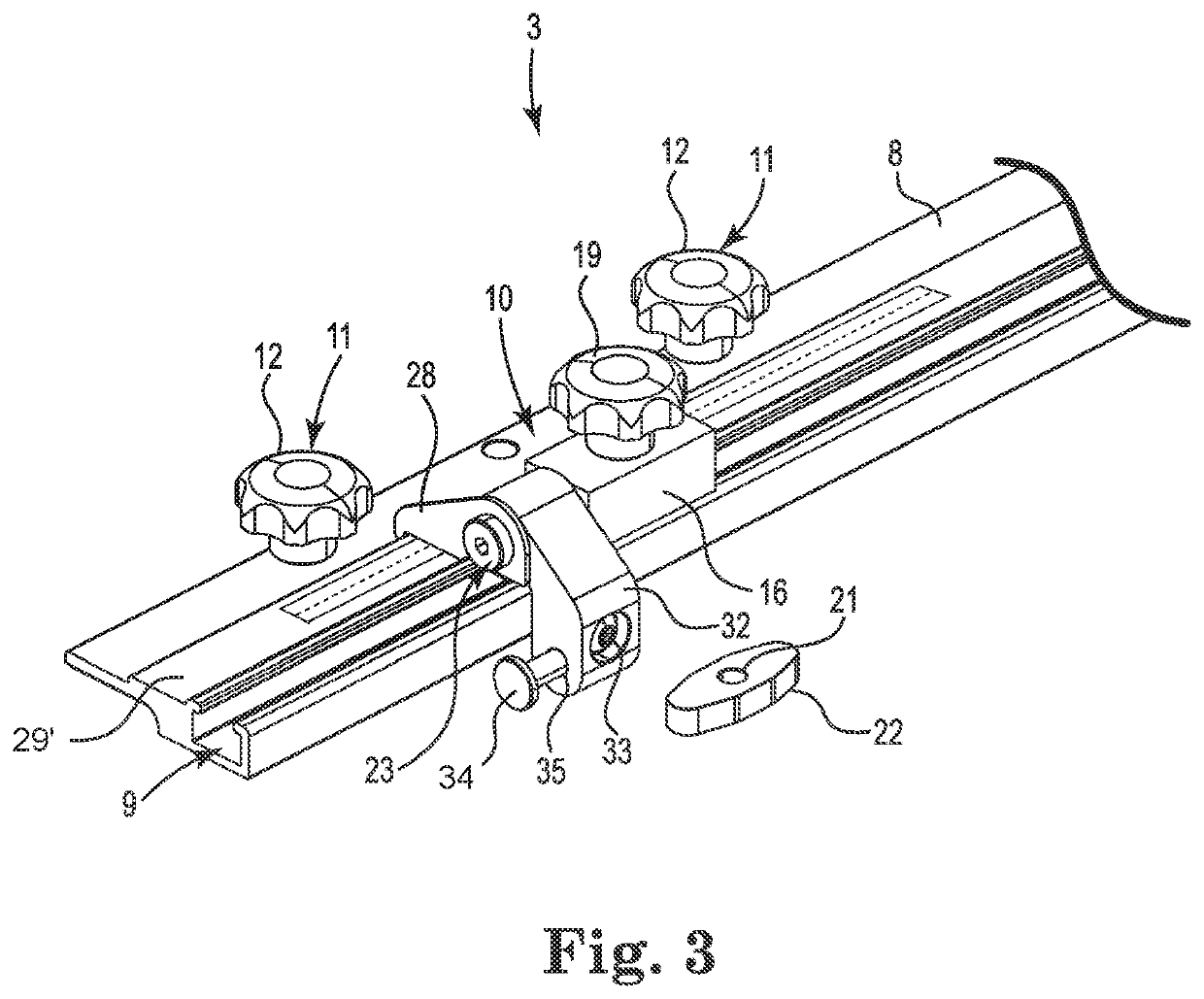
[0021]Referring generally to FIGS. 1-5 it will be appreciated that parallel and square alignment tools of the present disclosure generally may be embodied within various configurations and used in various ways to enhance the convenience of users. Indeed, while acknowledging that all of the example configurations of parallel and square alignment tools need not be shown herein, examples are provided to better demonstrate that a variety of configurations and methods of use are contemplated.

[0022]Turning to a first example...


PUM


Abstract

An alignment tool is disclosed for connection to a work component and for use in aligning the work component with a work piece to establish a repeatable set up for cutting or routing of the work piece, and wherein the alignment tool provides for parallel and square alignment of the work component relative to first and second edges of the work piece that are perpendicular to each other. Use of the parallel and square alignment tool aligns the work component for an operation parallel to the second edge of the work piece and the operation may be conveniently repeated on further work pieces without need to measure and mark the work pieces. Optional use of first and second parallel and square alignment tools along opposed second and third edges of a work piece that are perpendicular to a first edge provides for greater accuracy for operations having a greater length.

Description

BACKGROUND OF THE INVENTIONField of the Invention[0001]The present invention generally relates to tools that provide temporary or longer term connection to a work component to establish a precision gage or guide, and more particularly a quick and accurate way to removably join a parallel and square alignment tool to a work component by using complementary reference surfaces.Discussion of the Prior Art[0002]The alignment and connection of separate elements of tools, fixtures, and guide assemblies often relies on use of channels, such as in the form of T-shaped slots, commonly referred to as “T-slots”, in one or more of the components to be connected for temporary or longer-term use. This has been satisfactory for many uses but has serious limitations when precision and sturdiness of the connections are required. A common limitation with such prior art configurations relates to tools which aid only one but not all of the steps required to align both the square orientation of a sawcut ...

Claims


Application Information

Patent Timeline
Patent Type & Authority Patents(United States)
IPC IPC(8): B27B9/04B23Q9/00
CPCB27B9/04B23Q9/0014
Inventor FRIEDEBACH, ADOLF HANSHEIDT, WILLIAM D.
Owner TSO PROD LLC
Learn More