Light emitting module
a technology of light emitting modules and light emitting devices, which is applied in the direction of lighting and heating apparatus, planar light sources, instruments, etc., can solve the problems of large heat emission of light emitting devices and cracks in light emitting devices, and achieve the effect of suppressing crack generation and increasing durability
- Summary
- Abstract
- Description
- Claims
- Application Information
AI Technical Summary
Benefits of technology
Problems solved by technology
Method used
Image

Examples
first embodiment
Liquid Crystal Display 1000
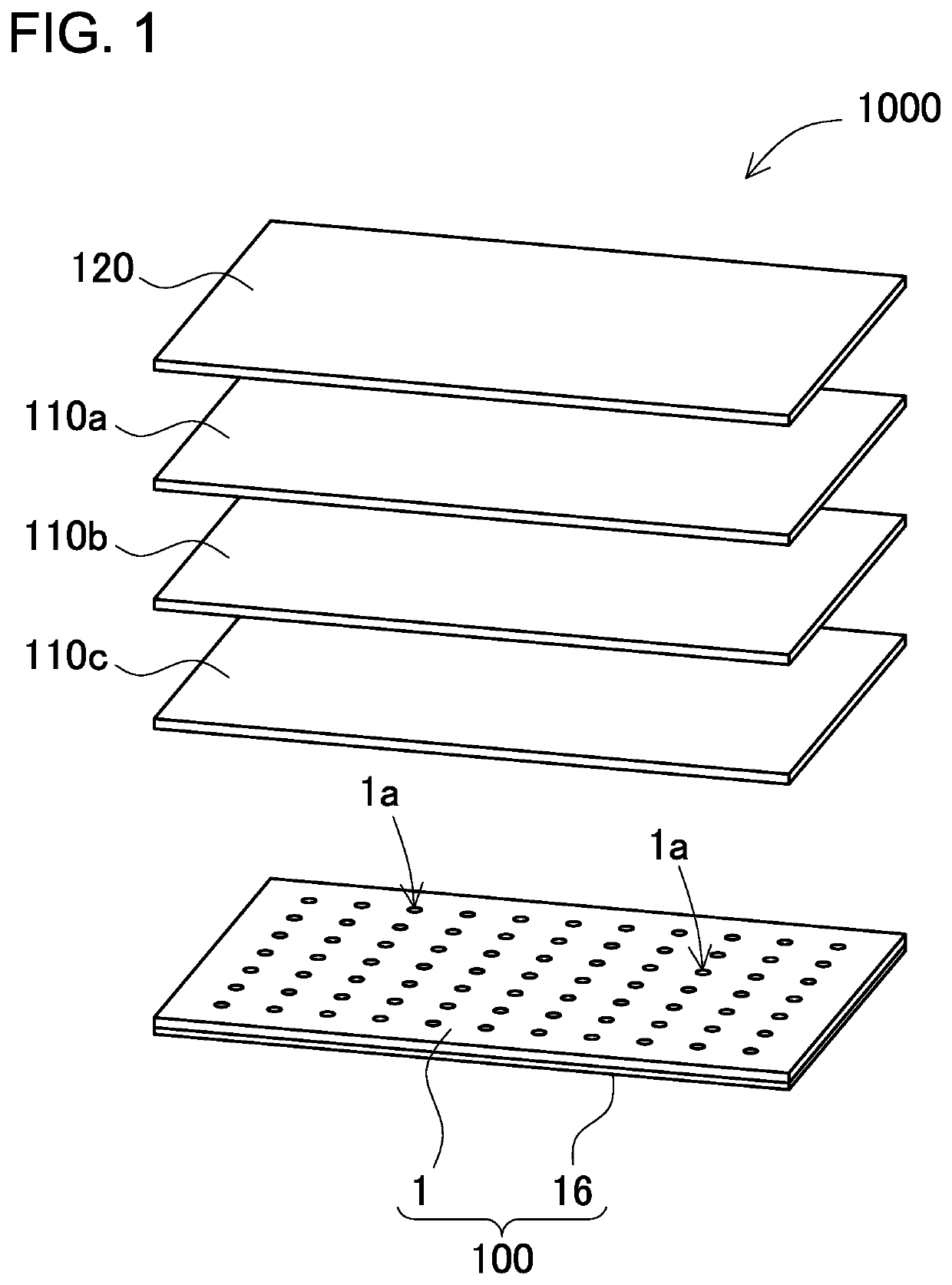
[0042]FIG. 1 is a schematic view showing components of a liquid crystal display 1000 which includes a light emitting module 100. The liquid crystal display 1000 includes a liquid crystal panel 120, two lens sheets 110a and 110b, a light diffusion sheet 110c, and the light emitting module 100 in this order from the top side. The liquid crystal display 1000 shown in FIG. 1 is a so-called direct-backlight type liquid crystal display, which includes the liquid crystal panel 120 and the light emitting module 100 arranged under the liquid crystal panel 120. The liquid crystal panel 120 is irradiated with light which is emitted by the light emitting module 100 in the liquid crystal display 1000. The liquid crystal panel can include a polarizing film, a color filter, and the like in addition to the aforementioned components.
Light Emitting Module 100
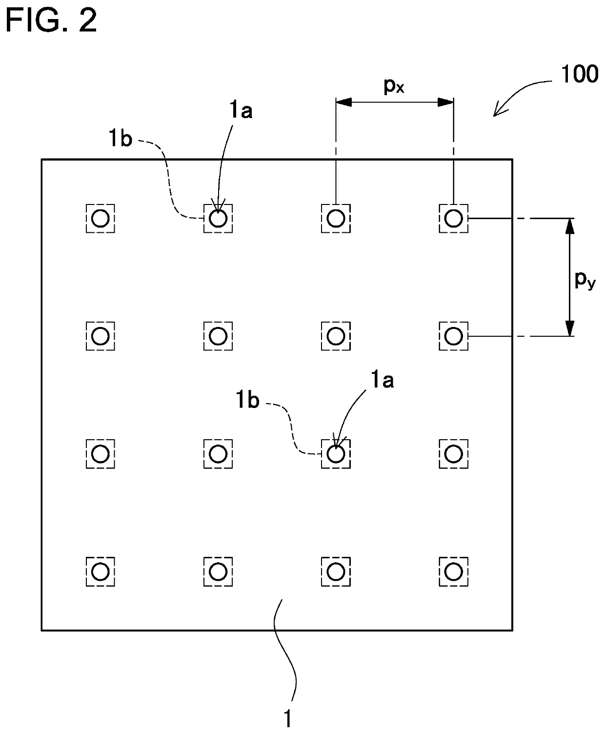
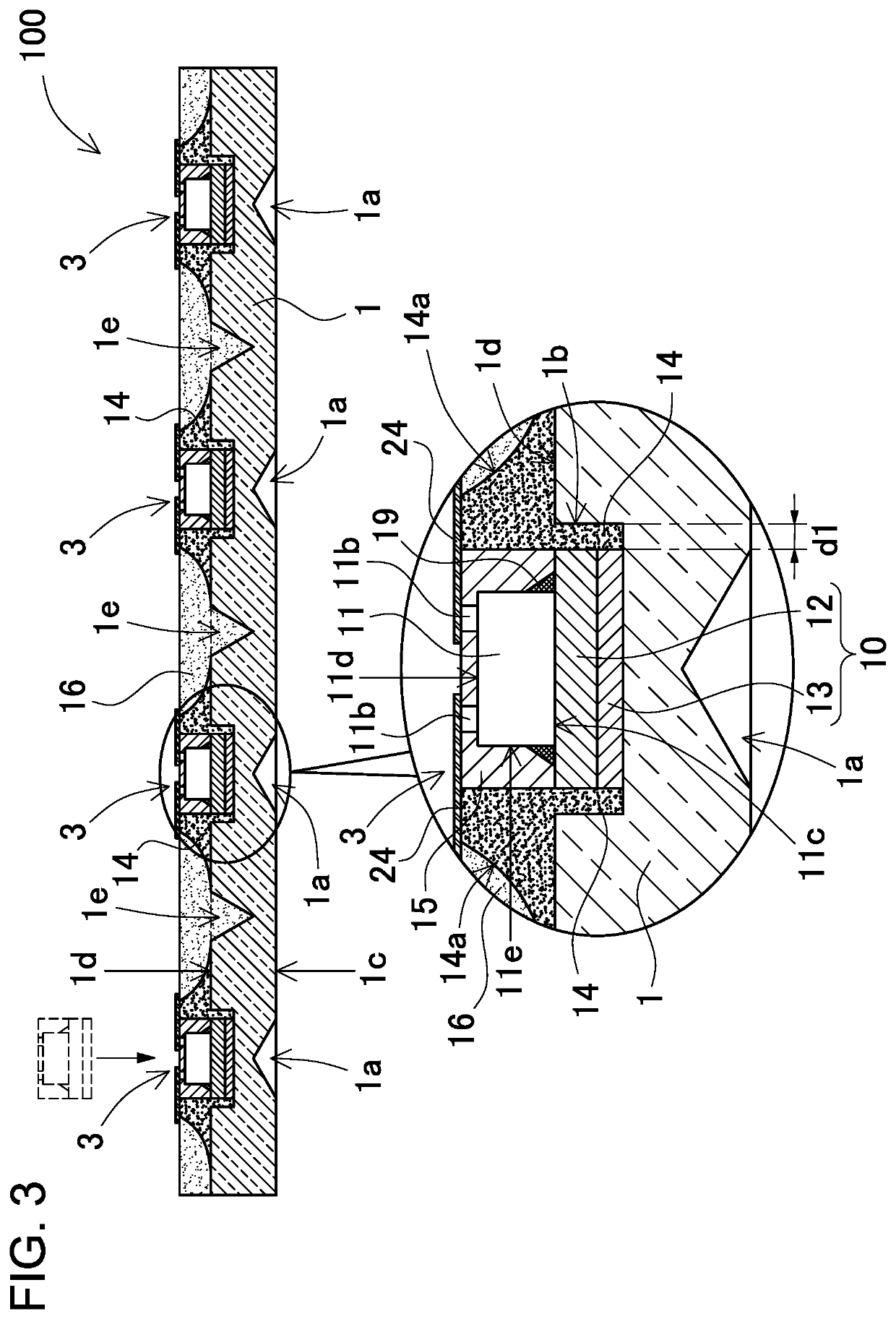
[0043]FIGS. 2 and 3 show the construction of the light emitting module 100 according to this embodiment. The light em...
second embodiment
[0098]The inclined surface of the interposition member can have a straight line as viewed in a cross-sectional view. This type of light emitting module according to a second embodiment is shown in a schematic cross-sectional view of FIG. 6. The components according to this illustrated light emitting module similar to the foregoing first embodiment are attached with the same reference signs as the first embodiment, and their description is omitted. Because an inclined surface 14a′ which serves as the interface between the interposition member 14 and the second light-reflection member 16 is formed in a flat shape, the flat parts of the interposition member 14 and the second light-reflection member 16 which are fixed onto each other can be large. Therefore, effects such as adhesive strength improvement can be obtained.
third embodiment
[0099]The inclined surface of the interposition member can be also a convex surface (a convex upward curve as viewed in a cross-sectional view), in other words, its curve protrudes toward the second light-reflection member 16 in a cross-sectional view. This type of light emitting module according to a third embodiment is shown in a schematic cross-sectional view of FIG. 7. The components according to this illustrated light emitting module similar to the foregoing first embodiment or the like are also attached with the same reference signs as the first embodiment, and their description is omitted. In this embodiment, a larger amount of resin is applied for an inclined surface 14a″ of the interposition member 14 so that the inclined surface 14a″ bulges. As a result, the inclined surfaces 14a″ can be formed in a convex lens shape. This shape can provide an effect of promoting light propagation in the lateral directions of the light guide plate 1.
[0100]Here, it is noted that, as shown i...
PUM
| Property | Measurement | Unit |
|---|---|---|
| width | aaaaa | aaaaa |
| width | aaaaa | aaaaa |
| width | aaaaa | aaaaa |
Abstract
Description
Claims
Application Information
 - R&D Engineer
- R&D Manager
- IP Professional
- Industry Leading Data Capabilities
- Powerful AI technology
- Patent DNA Extraction
Browse by: Latest US Patents, China's latest patents, Technical Efficacy Thesaurus, Application Domain, Technology Topic.
© 2024 PatSnap. All rights reserved.Legal|Privacy policy|Modern Slavery Act Transparency Statement|Sitemap