Bearing block assembly for a plant trimming machine

a technology of plant trimming machine and assembly, which is applied in the field of bearing blocks, can solve the problems of time-consuming and labor-intensive, and achieve the effect of reducing labor intensity and reducing labor intensity

Active Publication Date: 2020-12-08
KEIRTON
View PDF21 Cites 8 Cited by
  • Summary
  • Abstract
  • Description
  • Claims
  • Application Information

AI Technical Summary

Problems solved by technology

Setting the positions of the reel and bed knife correctly during re-assembly is time-consuming and requires highly-skilled labor.

Method used


Image

  • Bearing block assembly for a plant trimming machine
  • Bearing block assembly for a plant trimming machine
  • Bearing block assembly for a plant trimming machine

Examples


Embodiment Construction

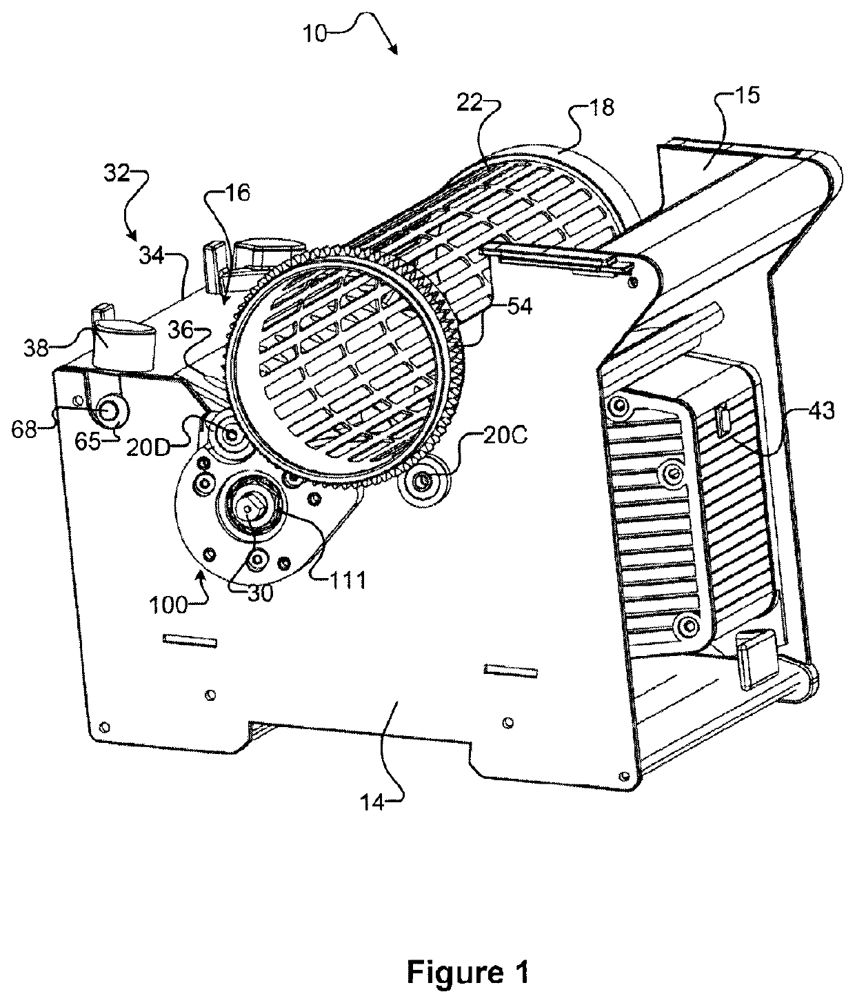
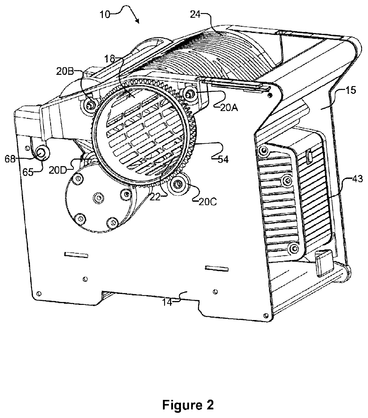
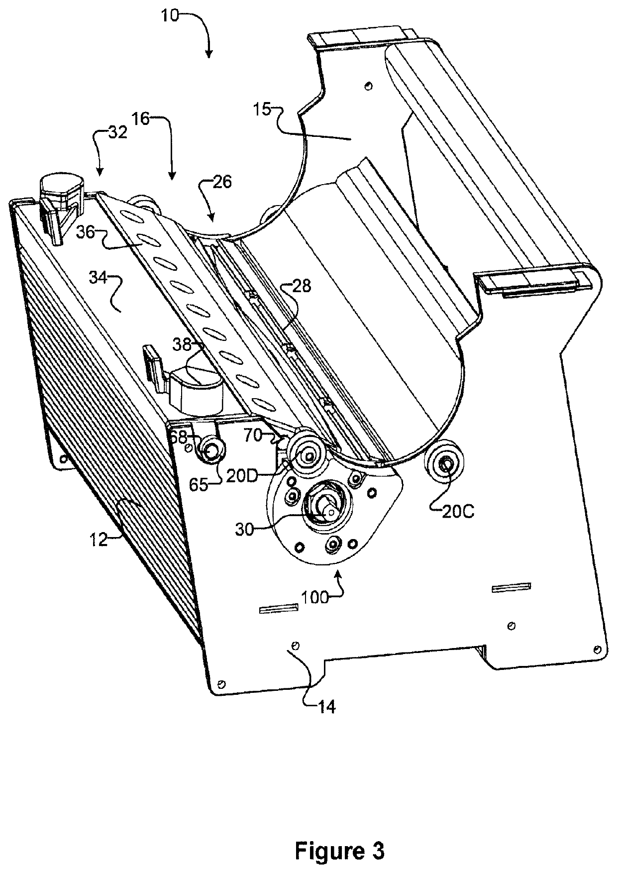
[0020]Referring first to FIGS. 1 to 4, a plant trimming machine 10 which incorporates the bearing block assemblies 100, 102 of the invention has a front plate 12, two end plates 14, 15 mounted on the left and right sides respectively of the machine 10, a cutting mechanism 16 removably mounted on the end plates 14, 15, and a removable rotatable tumbler 18, having a plurality of holes 22, adjacent to the cutting mechanism 16. The plant trimming machine 10 has a removable lid 24, shown in FIG. 2, to cover the tumbler 18 and the cutting mechanism 16.

[0021]The cutting mechanism 16 (best seen in FIG. 4) includes a reel 26, a bed bar 34 and a bed knife 36. The bed knife 36 is bolted to the bed bar 34 to form a bed bar assembly 32. The reel 26 comprises several helical blades 28 that are mounted to a rotatable shaft 30. The reel 26 is positioned adjacent to the bed bar assembly 32 and the tumbler 18.

[0022]Tumbler support wheels 20A, 20B, 20C and 20D positioned at each end of the tumbler 18 ...


PUM


Abstract

A bearing block assembly for a plant-trimming machine having a rotatable perforated tumbler, a rotatable reel and a bed bar assembly. The bearing block assembly comprises an outer bearing plate having a bearing-receiving bore for holding a reel bearing to rotatably support an end of the reel, and an inner bearing plate affixed to the outer bearing plate. The inner bearing plate has a pocket for receiving the bearing-receiving bore of the outer bearing plate, the pocket having a tolerance permitting the bearing-receiving bore to be set at a selected position within the pocket. The bearing block assembly has connectors for affixing the outer bearing plate to the inner bearing plate. The bearing block assembly sets the positions of the reel, bed knife and tumbler correctly during assembly of the plant-trimming machine, reducing the time and skill required for maintenance.

Description

TECHNICAL FIELD[0001]The present invention pertains to bearing blocks, and in particular, to bearing block assemblies for plant trimming machines.BACKGROUND[0002]It is known in the plant-trimming art to employ a plant trimming machine which comprises a rotatable perforated tumbler and a cutting mechanism that includes a rotatable reel with helical blades, and a bed bar with a bed knife. In operation, plant material such as aromatic herbs that requires trimming is fed into the rotating tumbler, parts of the plant material protrude through the perforations in the tumbler, and the cutting mechanism cuts the protruding plant material in a scissor-like shearing action as the helical blades of the rotatable reel pass over the stationary bed knife. Examples of such machines are disclosed in WO 2014 / 183209, WO 2014 / 190425 and WO 2015 / 003256.[0003]In conventional plant-trimming machines of this type, the rotatable reel is supported at each end by bearing blocks that are affixed to the respec...

Claims


Application Information

Patent Timeline
Patent Type & Authority Patents(United States)
IPC IPC(8): A01G3/00B02C17/18A23N15/00A01G3/037B02C17/00B02C17/02
CPCB02C17/181B02C17/002A23N15/00B02C17/02A01G3/037A01G3/00A01G2003/005
Inventor INGRAM, ERIK
Owner KEIRTON
Why Eureka
Try Eureka