Apparatus and method for calibrating driver monitoring camera
a technology for monitoring cameras and apparatus, applied in the field of apparatus and methods for calibrating driver monitoring cameras, can solve the problem that the state of the driver cannot be monitored, and achieve the effect of convenient calibration
- Summary
- Abstract
- Description
- Claims
- Application Information
AI Technical Summary
Benefits of technology
Problems solved by technology
Method used
Image
Examples
first embodiment
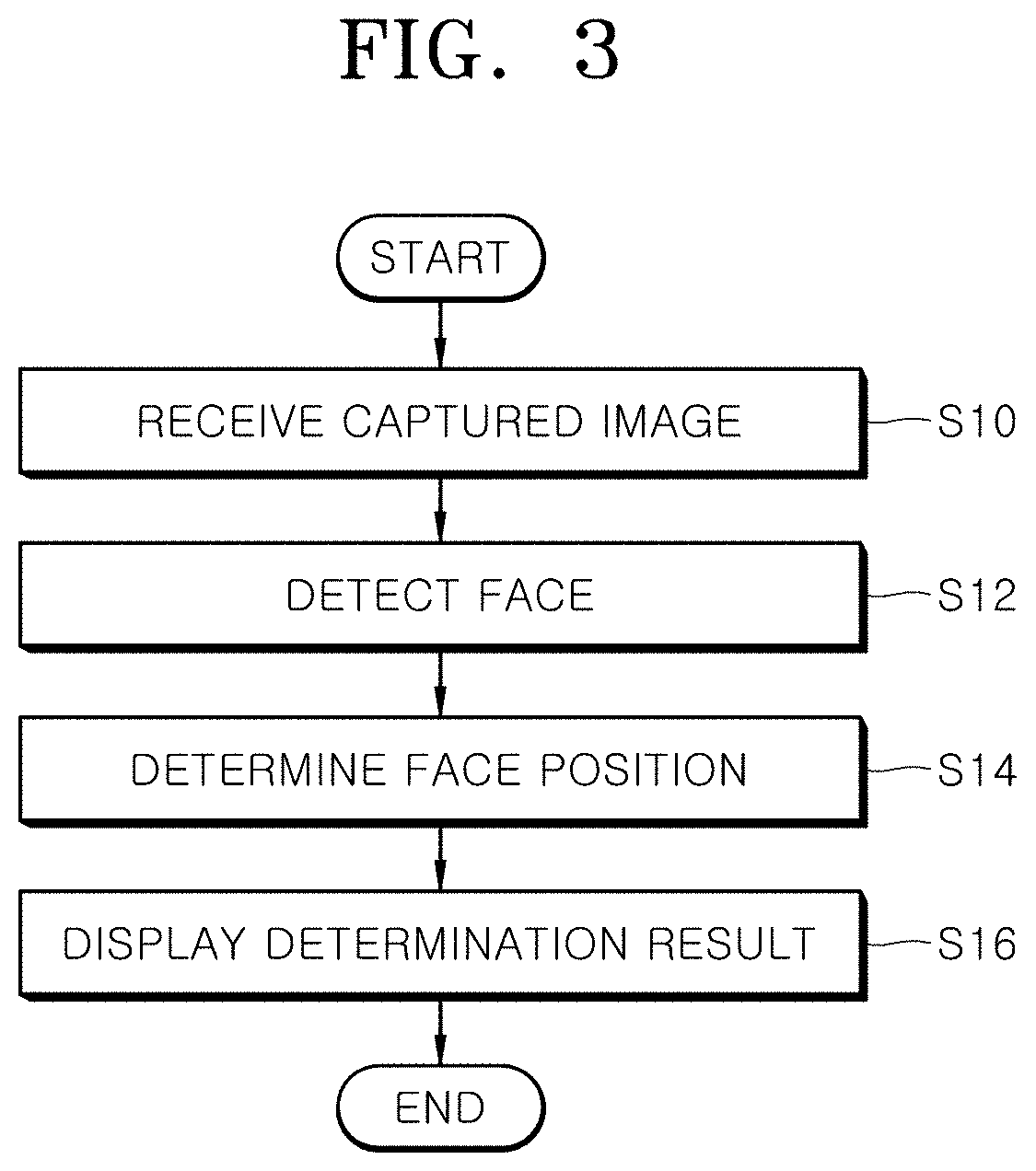
[0064]FIG. 3 is a flowchart for describing a method for calibrating a driver monitoring camera in accordance with the present invention.
[0065]As illustrated in FIG. 3, the method for calibrating a driver monitoring camera in accordance with the first embodiment of the present invention may begin with step S10 in which the control unit 20 receives a captured image from the camera 10.
[0066]After receiving the captured image in step S10, the control unit 20 may detect the face of a driver from the captured image in step S12.
[0067]After detecting the face of the driver in step S12, the control unit 20 may determine the position of the face detected from the image in step S14.
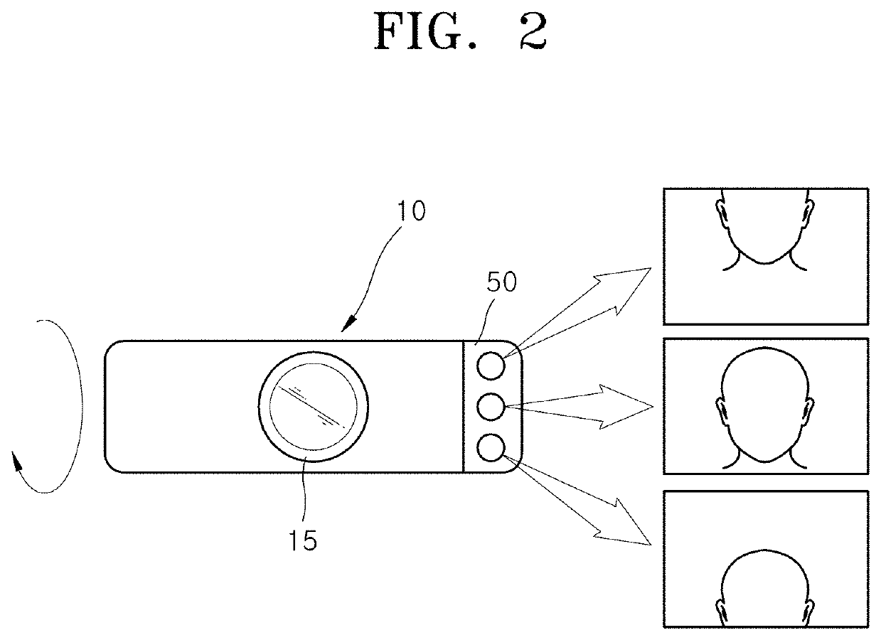
[0068]That is, the control unit 20 may determine whether the face is positioned in the center or at the top or bottom of the image.
[0069]After determining the position of the face in step S14, the control unit 20 may display the position of the detected face as a vertical position through the display unit 30 as illu...
second embodiment
[0072]FIG. 4 is a flowchart for describing a method for calibrating a driver monitoring camera in accordance with the present invention.
[0073]As illustrated in FIG. 4, the method for calibrating a driver monitoring camera in accordance with the second embodiment of the present invention may begin with step S20 in which the control unit 20 receives a captured image from the camera 10.
[0074]After receiving the captured image in step S20, the control unit 20 may detect features of the background from the captured image in step S22.
[0075]The features of the background may include one or more of a window frame, roof, B pillar, handle and fixed structure of the vehicle. When the features are detected as fixed structures in the vehicle through image processing, the angle of the camera 10 may be recognized.
[0076]Although the background is generally considered as unnecessary information, the apparatus and method in accordance with the present embodiment may detect the fixed structures in the...
third embodiment
[0079]FIG. 5 is a flowchart for describing a method for calibrating a driver monitoring camera in accordance with the present invention.
[0080]As illustrated in FIG. 5, the method for calibrating a driver monitoring camera in accordance with the third embodiment of the present invention may begin with step S30 in which the control unit 20 determines a vehicle state.
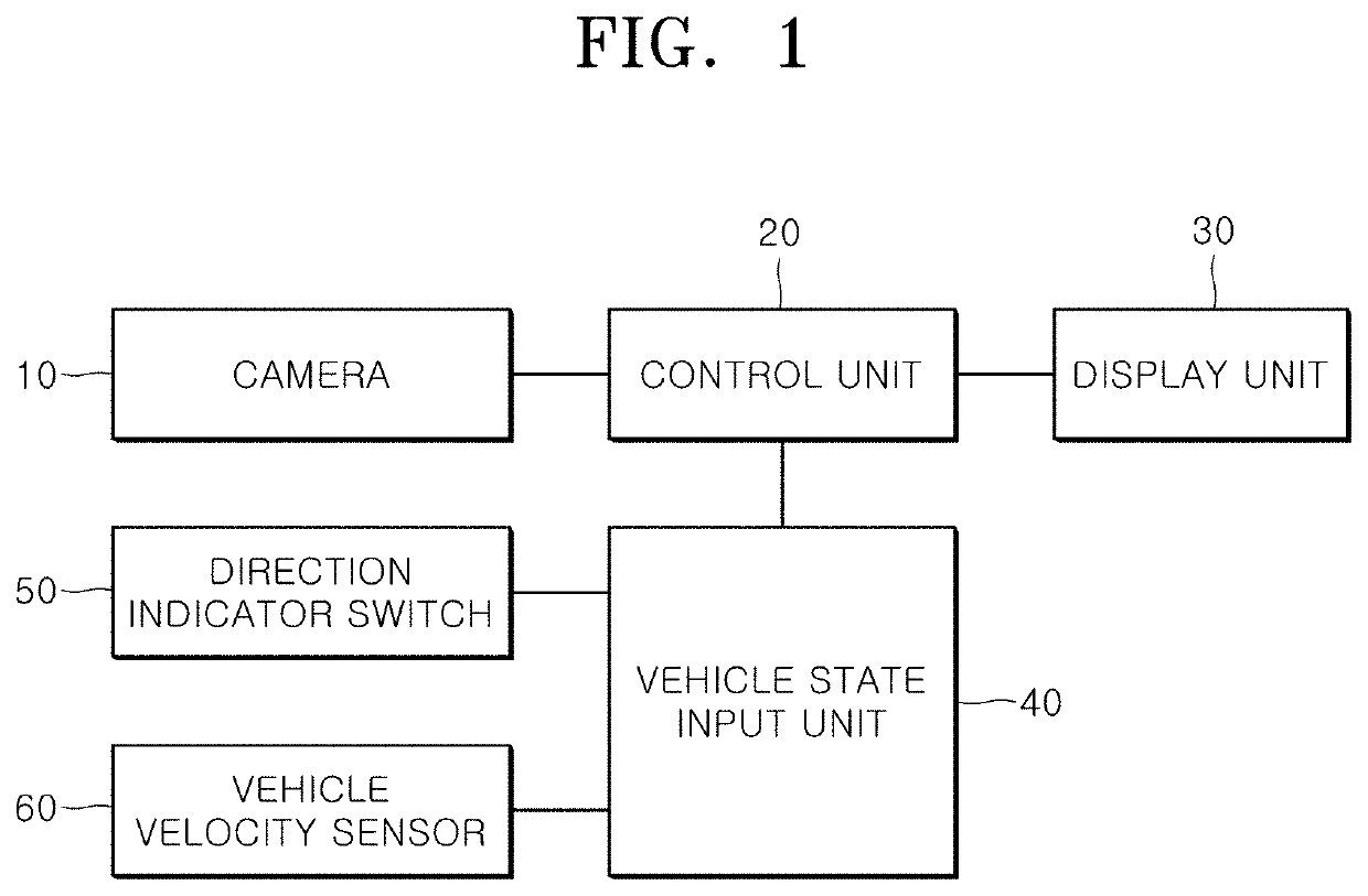
[0081]The control unit 20 may receive a direction indication state and vehicle speed state from the direction indicator switch 50 or the vehicle speed sensor 60 through the vehicle state input unit 40, and determine the vehicle state.
[0082]When it is assumed that the driver operates the direction indicator switch 50 to the left and necessarily looks at the left side mirror at least once in the case that the driver intends to make a left turn during driving and when it is assumed that the driver operates the direction indicator switch 50 to the right and necessarily looks at the right side mirror at least once in the case t...
PUM
 Abstract
Description
Claims
Application Information
 - R&D
- Intellectual Property
- Life Sciences
- Materials
- Tech Scout
- Unparalleled Data Quality
- Higher Quality Content
- 60% Fewer Hallucinations
Browse by: Latest US Patents, China's latest patents, Technical Efficacy Thesaurus, Application Domain, Technology Topic, Popular Technical Reports.
© 2025 PatSnap. All rights reserved.Legal|Privacy policy|Modern Slavery Act Transparency Statement|Sitemap|About US| Contact US: help@patsnap.com


