
Flavor inhaler

a flavor inhaler and inhaler technology, applied in the field of flavor inhalers, can solve the problem of excessive heat supplied to the flavor source, and achieve the effect of reducing costs

Active Publication Date: 2020-12-22
JAPAN TOBACCO INC
View PDF13 Cites 0 Cited by
  • Summary
  • Abstract
  • Description
  • Claims
  • Application Information

AI Technical Summary

Benefits of technology

[0006]The members for holding a combustion type heat source and a flavor source disclosed in U.S. Pat. No. 5,105,831 and WO 2015 / 174442 are both made of a heat conduction material such as a metal. Therefore, excessive heat is supplied to the flavor source in some cases or there are variations in the manner in which heat is transferred depending on locations. Therefore, there is still a room for improvement on the flavor inhaler having such a conventional cup member in terms of weight reduction and cost reduction.
[0007]With the foregoing in view, it is an object of the present invention to provide a technique for reducing the weight and cost of a flavor inhaler while preventing excessive heat transfer to the flavor source and reducing the variations of the heat transfer.
[0010]According to the present invention, a cup member for holding a flavor source is made of a material including pulp and a binder, and a heat conduction member is further provided between the cup member and the holding member to cover at least a part of the combustion type heat source and at least apart of a side surface of the cup member, so that abrupt heat transfer to the flavor source and variations in the heat transfer can be suppressed, and the flavor inhaler can have a reduced weight and can be produced less costly.

Problems solved by technology

Therefore, excessive heat is supplied to the flavor source in some cases or there are variations in the manner in which heat is transferred depending on locations.

Method used


Image

  • Flavor inhaler
  • Flavor inhaler
  • Flavor inhaler

Examples


first embodiment

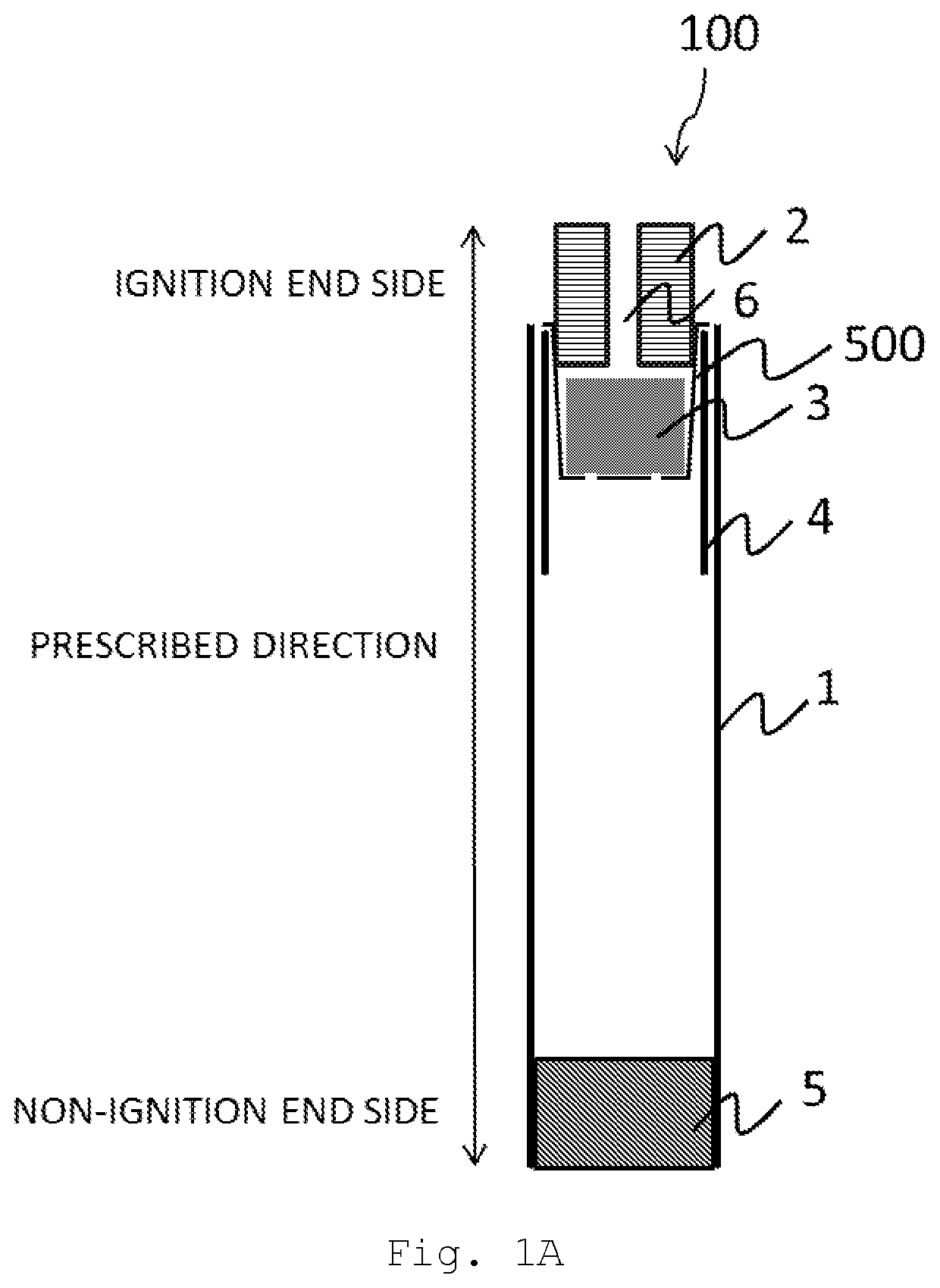
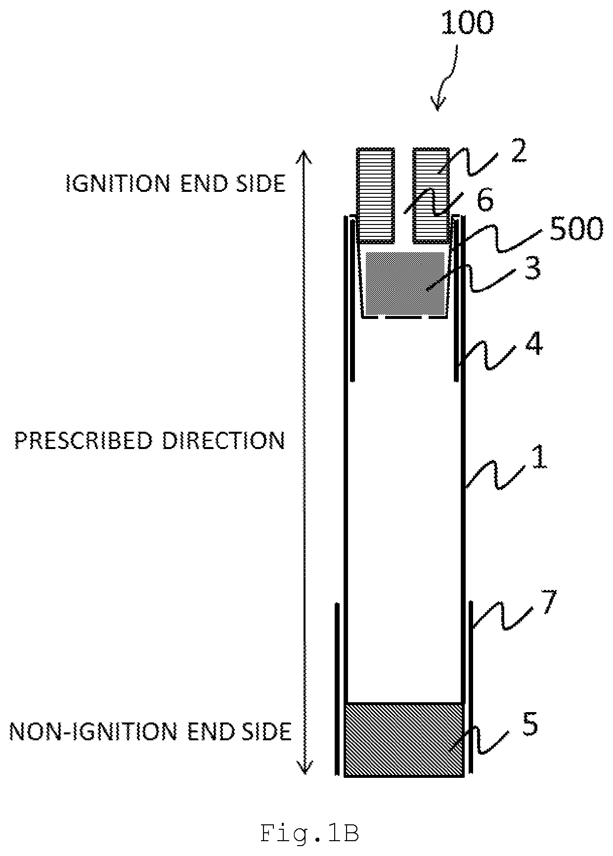
[0019]FIG. 1A is a view of a flavor inhaler 100 according to a first embodiment of the present invention. FIG. 2 is a view of a cup member 500 according to the first embodiment.

[0020]As shown in FIG. 1A, the flavor inhaler 100 includes a holding member 1, the cup member 500, a combustion type heat source 2, a flavor source 3, a heat conduction member 4, and a filter 5. According to the first embodiment, the flavor inhaler 100 does not require combustion of a flavor source.

[0021]The holding member 1 has a tubular shape which extends in a prescribed direction from an ignition end to a non-ignition end. For example, the holding member 1 has a cylindrical shape or a rectangular tube shape.

[0022]The holding member 1 may be a paper tube formed by rolling a rectangular paper sheet into a cylindrical shape and putting the edges of the paper sheet together. The kind of paper for the holding member 1 is not particularly limited but the paper is preferably paperboard. More specifically, it is ...

second embodiment

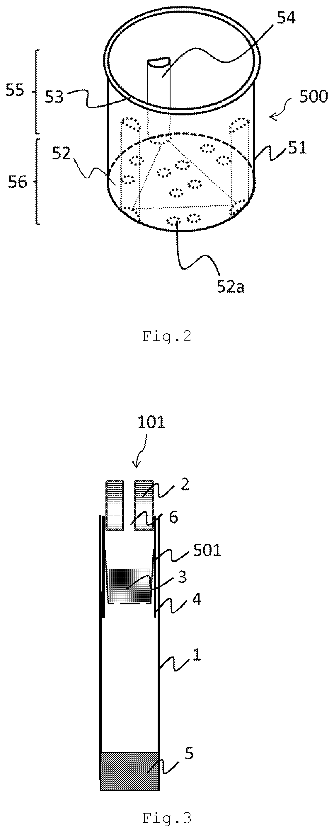
[0092]FIG. 3 is a view of a flavor inhaler according to a second embodiment of the invention. The elements are the same as those of the first embodiment, and the flavor inhaler 101 includes a holding member 1, a cup member 501, a combustion type heat source 2, a flavor source 3, a heat conduction member 4, and a filter 5.

[0093]The following description concentrates on the cup member 501 which is different from the first embodiment. According to the second embodiment, the cup member 501 does not have a flange protruding outwardly from the cup member 501 from the outer circumference of the opening. The side wall of the cup member 501 is tilted to forma tapered shape so that the diameter of the opening of the cup member 501 on the ignition end side is greater than the diameter of the bottom plate.

[0094]The same conditions as the first embodiment may be applied as for the size of the cup member 501, the thicknesses of the side wall and the bottom plate, and their ratios.

[0095]The same c...

third embodiment

[0102]FIG. 4 is a view of a flavor inhaler according to a third embodiment of the present invention.

[0103]The basic elements are substantially identical to those of the first and second embodiments, and the flavor inhaler 102 includes a holding member 1, a cup member 502, a combustion type heat source 2, a flavor source 3, a heat conduction member 4, and a filter 5.

[0104]According to the first and second embodiments, the cup member 500 or 501 is inserted in the holding member 1 so that the opening of the cup member is positioned on the ignition end side, while according to the third embodiment, the cup member 502 is inserted in the holding member 1 so that the opening of the cup member is positioned on non-ignition end side. Note that according to the third embodiment, the combustion type heat source 2, the flavor source 3, and the cup member 502 may previously be aligned and then rolled up by the holding member 1 (may be produced by rolling).

[0105]FIG. 5 is a view of the cup member...


PUM


Abstract

The purpose of the present invention is to provide a technique which, while avoiding excessive conduction of heat to the flavor source, reduces variance of heat conduction, and which makes it possible to reduce the weight and the cost of the flavor inhaler. This purpose is met by a flavor inhaler which, provided with a cylindrical holding member which extends along a prescribed direction from a lighting end to a non-lighting end, comprises a combustion-type heat source which is disposed at the lighting end, a flavor source which, in the aforementioned prescribed direction, is arranged towards the non-lighting end with respect to the combustion-type heat source, a cup-shape cup member which holds the flavor source and has a side wall and a bottom plate, and a heat conductive member which covers at least a portion of the lateral surface of the cup member and the combustion-type heat source and is arranged between the cup member and the holding member, wherein the cup member is arranged with the bottom plate thereof disposed towards the non-lighting end with respect to the combustion-type heat source, and is inserted into the holding member oriented so as to open towards the lighting end or oriented so as to open towards the non-lighting end, and at least the side wall and the bottom plate configuring the cup member are configured from a material containing pulp and a binder.

Description

CROSS REFERENCE TO RELATED APPLICATIONS[0001]This application is a Continuation of PCT International Application No. PCT / JP2017 / 016307, filed on Apr. 25, 2017, which claims priority under 35 U.S.C. 119(a) to Patent Application No. PCT / JP2016 / 063201, filed in Japan on Apr. 27, 2016, all of which are hereby expressly incorporated by reference into the present application.BACKGROUND OF THE INVENTIONField of the Invention[0002]The present invention relates to a flavor inhaler which extends in a prescribed direction from an ignition end to a non-ignition end, and particularly to a flavor inhaler having a cup member for holding a flavor source.[0003]A flavor inhaler used to taste flavor without burning a flavor source such as tobacco has been proposed as a cigarette substitute. For example, a flavor inhaler generally includes a combustion type heat source which extends in the direction from an ignition end to a non-ignition end (hereinafter as the “lengthwise direction”), a flavor source ...

Claims


Application Information

Patent Timeline
Patent Type & Authority Patents(United States)
IPC IPC(8): A24F47/00A24B15/16A24D1/22
CPCA24F47/00A24B15/165A24F40/30A24B15/16A24F40/42A24D1/22A24F42/10A24F42/60A61M15/06A24D1/002
Inventor AKIYAMA, TAKESHIODA, TAKASHI
Owner JAPAN TOBACCO INC
Learn More