Pyrolysis boiler

a boiler and pyrolysis technology, applied in the field of heat power engineering, can solve the problems of increasing the cost, slow water boiling, and increasing the cost of heating devices, and achieve the effects of low carbon monoxide emissions, low cost, and high heat transfer efficiency

Active Publication Date: 2020-12-22
PYROHEAT OU
View PDF21 Cites 0 Cited by
  • Summary
  • Abstract
  • Description
  • Claims
  • Application Information

AI Technical Summary

Benefits of technology

[0015]The technical results that can be achieved with the proposed claimed invention are: a stable and controlled gasification of wood fuel with a natural (i.e., high) moisture content, complete and clean combustion of pyrolysis gas (with minimal emissions of carbon monoxide and soot) in combination with a high efficiency of heat transfer to the heat transfer fluid and minimal dimensions and weight of the structure.

Problems solved by technology

At the same time, the design has several disadvantages, because water, the temperature of which cannot exceed 100° C, is in direct contact with the external walls of the fuel hopper and the gasification chamber; wherein the main disadvantage can be phrased as follows: “something that should be very hot is cooled”.
The practical consequences of this are the low efficiency and instability of the solid fuel gasification process, the need to use wood that has been dried for years and has a moisture content of up to 20% (which the conscientious manufacturer notifies the users about), deposits of tar and ash on the walls of the fuel hopper and gasification chamber, which increases the cost and complicates the operation of the heating device.
In addition, direct contact of the heat-transfer fluid (water) with the walls of the gasification chamber, which contains tens or even hundreds of kilograms of hot coal, can lead to rapid water boiling and to an explosion of the boiler in the event of an emergency failure of the forced circulation system.
For preventing this danger, additional systems need to be installed in the heating device composition, which again makes it more complicated and expensive.
In addition to the aforementioned disadvantages of direct contact of the heat-transfer fluid with the walls of the hopper and the gasification chamber, the disadvantages of this technical solution are: the complexity and high cost of manufacturing a spiral chamber (double curvature surface) of heat-resistant steel, a lack of preheating for the secondary air pumped into the combustion chamber, as well as the high complexity of cleaning the internal surfaces of the hopper and the gasification chamber.
The disadvantages of this technical solution are: use of a heat exchanger circuit (liquid in a spiral pipe surrounded by the slow flow of hot combustion products) that is inefficient in terms of heat transfer, high complexity of maintenance (cleaning of soot) for such a heat exchanger, the extremely difficult transfer of heat from the pyrolysis gas combustion zone to the bottom of the gasification chamber with a thick layer of thermal insulation.
The disadvantages of this technical solution are: a selection of a direct (ascending) gasification scheme that is not optimal for gasifying wood fuel, no heating of secondary air, the extremely uneven composition of the gas mixture in the combustion chamber due to the supply of secondary air at one point of the annular chamber, hampered by to the presence of a wide air gap during the heat transfer from the combustion zone to the “water jacket”.
Thus, the embodiment of the described technical solution is impossible without additional inventive activity, which calls into question the legality of the patent issuance.
Even if the use of expensive heat-resistant steels allows to prevent the destruction of the structure, this mode of operation (forced and uncontrollable) does not meet the requirements of the users of the heating devices.
Tests with this design showed that the adopted scheme for transferring the pyrolysis gas combustion heat into the gasification chamber (only from the bottom of the gasification chamber) does not provide the temperature regime required for the gasification of particularly difficult types of fuel (for example, raw chips at 50% moisture content) over the entire height of the gasification chamber.
In addition, the proposed scheme for transferring heat to the heat transfer fluid (mass transfer of hot combustion products mixed with excess air) requires the use of a heavy and large fire-tube heat exchanger.

Method used


Image

  • Pyrolysis boiler
  • Pyrolysis boiler

Examples


Embodiment Construction

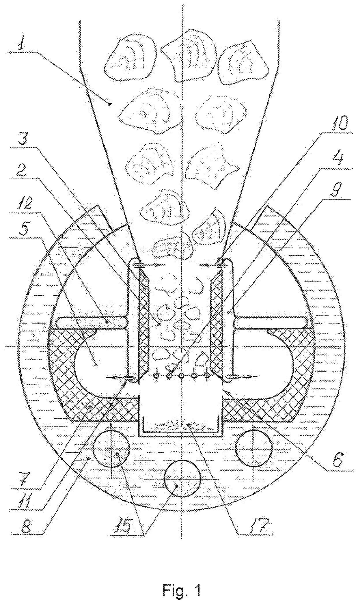
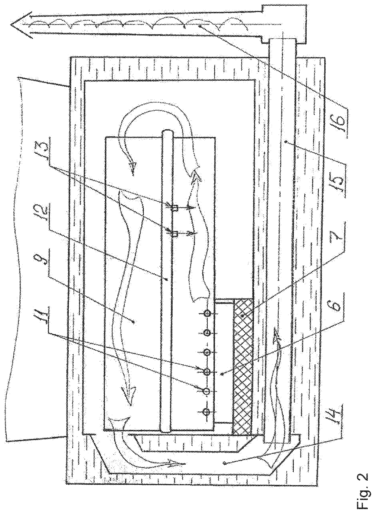
[0032]The pyrolysis boiler contains a hopper for solid fuel 1, a gasification chamber 2 with a heat-resistant thermal insulation coating 3 and a pyrolysis gas exit window with a grate 4, two compartments of the pyrolysis gas combustion chamber 5 with horizontal slots 6 and figured heat-resistant inserts 7, a cavity with water 8 surrounding the combustion chamber, air ducts 9 made in the form of flat ducts with nozzle openings for supplying primary air 10 and secondary air 11 installed in the form of a longitudinal horizontal partition in the compartments of the combustion chamber, flat box-shaped air ducts 12 with nozzle openings for supplying additional secondary air 13, gas flue 14, flame tubes 15, smoke pipe 16, ash collection box 17 installed below the grate.

[0033]The pyrolysis boiler works as follows: Solid fuel (for example, firewood or wood chips with a natural moisture content) is loaded into the hopper 1. Due to gravity, wood fuel goes down, successively passing through the...


PUM


Abstract

Heat and power engineering, specifically being heating devices includes a pyrolysis boiler, in which, wood is subjected to high-temperature gasification and pyrolysis with subsequent burning off of pyrolysis gases. A stable and controllable gasification of wood with a natural high moisture content is achieved, and at the same time, a highly efficient transfer of combustion heat to a liquid heat-transfer agent is obtained. A gasification chamber is positioned between two compartments of a pyrolysis gas combustion chamber of the pyrolysis boiler, while the external wall of the combustion chamber is used as a heat-transfer surface, and at the same time, neither the fuel bunker nor the gasification chamber are in contact with water.

Description

PRIORITY[0001]This application is a U.S national application of the international application number PCT / RU2017 / 000605 filed on Sep. 5, 2017 and claiming priority of Russian national application RU2016137008 filed on Sep. 15, 2016 the contents of all of which are incorporated herein by reference.FIELD OF INVENTION[0002]The invention relates to heat power engineering, in particular to heating devices, in which solid fuel of plant origin (firewood, wood waste, chips, straw) is subjected to high-temperature gasification (pyrolysis) followed by the combustion of pyrolysis gases.BACKGROUND OF THE INVENTION[0003]Prior art describes a pyrolysis (gasification) boiler, containing a hopper for solid fuels, a gasification chamber and a pyrolysis gas combustion chamber united by a common double-walled vertical housing with heat-transfer fluid (water) circulating between these walls. The vast majority of commercially available pyrolysis boilers are made according to this scheme, for example, pro...

Claims


Application Information

Patent Timeline
Patent Type & Authority Patents(United States)
IPC IPC(8): F23B10/02F23G7/10F23G5/16F23L1/00F23L9/00F24H1/00F23G5/027
CPCF23L9/00F23G5/16F24H1/00F23L1/00F23B10/02F23G7/105F23G5/027F23G2201/303F23G2209/261F23G2202/103F23B50/06F23B90/06F23L9/02
Inventor SOLONIN, MARK
Owner PYROHEAT OU
Why Eureka
Try Eureka