Pulse-controlled inverter

a pulse-controlled inverter and power module technology, applied in the direction of dc-ac conversion without reversal, power conversion systems, electrical apparatus, etc., can solve the problems of increasing common-mode interference emissions and symmetrical embodiment of inverter power modules in particular, and achieves the effect of increasing common-mode interference emissions and little complexity

Active Publication Date: 2018-12-04
ROBERT BOSCH GMBH
View PDF8 Cites 0 Cited by
  • Summary
  • Abstract
  • Description
  • Claims
  • Application Information

AI Technical Summary

Benefits of technology

[0010]It is a concept of the present invention to provide a pulse-controlled inverter having minimal (common-mode) interference emission, in which the subcomponents in each case do not have to be arranged symmetrically per se with regard to their stray variables, i.e. stray capacitances and stray inductances. In this context, symmetry means that the stray variables of the components on the high side substantially correspond to those on the low side, i.e. the components are symmetrical between the high and low side in relation to their stray variables. Asymmetries in the subcomponents normally lead to increased common-mode interference emissions. The reason for this is that the asymmetries cause the commutation circuit currents of the system to undergo “differential mode-common mode conversion”.
[0011]Although DC link capacitors and busbars can be embodied symmetrically with relatively little complexity, the symmetrical embodiment of an inverter power module in particular presents a challenge. The present invention addresses this problem to a certain extent. The present invention is based on the knowledge that asymmetries that are present in subcomponents can be compensated for by “opposing” asymmetries in other subcomponents of the system. In this context, the system is not arranged symmetrically on the plane of the subcomponents but is symmetrical on the commutation circuit plane. Therefore, an asymmetry in an inverter power module that can only be avoided using complex means can be balanced out by correspondingly purposefully selected opposing asymmetries in the input circuit or the busbar arrangement. The input circuit and / or the busbar arrangement can each be appropriately adapted and optimized, building on the specific embodiment of the power module.
[0014]The solution according to the invention has the significant advantage that, inter alia, inexpensive, asymmetrical power modules can be used for a pulse-controlled inverter, without increasingly line-based interference emissions arising. Subsequently, less outlay in terms of filters etc. is required in order to satisfy the corresponding limit values for the electromagnetic compatibility (EMC). The system according to the invention is thus not only inexpensive, but is also characterized by high efficiency and improved energy balance, as power losses can be kept to a minimum. Pulse-controlled inverters according to the invention can be used in various fields of application of electric machines. For example, in addition to electric and hybrid electric vehicles, said pulse-controlled inverters according to the invention may also be used in inverter-energized industrial drives or the like.
[0019]In accordance with one development, the n-phase inverter module may have a bridge branch for each phase, each bridge branch being composed of a high-side power semiconductor switch and a low-side power semiconductor switch. This development is a possible simple form of the embodiment of an inverter module that is simple to control.

Problems solved by technology

Asymmetries in the subcomponents normally lead to increased common-mode interference emissions.
Although DC link capacitors and busbars can be embodied symmetrically with relatively little complexity, the symmetrical embodiment of an inverter power module in particular presents a challenge.

Method used


Image

  • Pulse-controlled inverter

Examples


Embodiment Construction

[0026]In the figures, identical reference numerals denote identical elements or elements having an identical function.

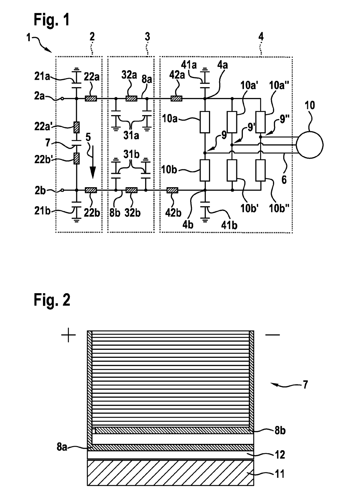
[0027]FIG. 1 shows a schematic illustration of an electric machine having a pulse-controlled inverter according to one embodiment of the invention.

[0028]In FIG. 1, the reference numeral 1 denotes a pulse-controlled inverter. The pulse-controlled inverter 1 is connected to an electric machine 10 and is embodied to supply said electric machine with a three-phase AC voltage (AC output voltage 6). For example, the electric machine 10 may be a synchronous or asynchronous machine of an electrically driven vehicle such as an electric car or a hybrid electric vehicle. However, it may also be possible here for the electric machine 10 of FIG. 1 to be used in stationary systems, for example in industrial drives, in power plants, in electrical energy recovery units, in energy storage units or similar systems. A further option for use of the electric machine 10 of FIG. 1 are gene...


PUM


Abstract

A pulse-controlled inverter with a circuit providing a DC voltage between high-side and low-side inputs. In one example, the circuit includes a first high-side stray capacitance and inductance and a first low-side stray capacitance and inductance. A busbar arrangement is configured to connect the high-side input to a high-side connection and the low-side input to a low-side connection. The busbar arrangement includes a second high-side stray capacitance and inductance and a second low-side stray capacitance and inductance. An inverter module is coupled to the high-side connection and the low-side connection and configured to convert the DC voltage into an AC voltage. The inverter module has a third high-side stray capacitance and inductance and a third low-side stray capacitance and inductance. The sum of the first, second, and third high-side stray capacitance and inductance is substantially equal to the sum of the first, second, and third low-side stray capacitance and inductance.

Description

BACKGROUND OF THE INVENTION[0001]The invention relates to a pulse-controlled inverter with minimized electromagnetic interference emission.[0002]Although the present invention and the problem on which it is based are explained on the basis of an electric vehicle having a pulse-controlled inverter, they are also applicable to any other electrical drive systems having clocked, electrically powered inverters.[0003]In an electrical drive system of an electric vehicle or a hybrid electric vehicle, a polyphase voltage is usually fed into an electric machine by an inverter, for example in the form of a pulse-controlled inverter. For this purpose, an energy storage device, such as a high-voltage battery, can energize a DC link circuit, which for its part provides a DC voltage that can be converted into a polyphase AC voltage, for example a three-phase AC voltage, in order to feed the electric machine.[0004]To that end, conventional pulse-controlled inverters (PCI) comprise typically at leas...

Claims


Application Information

Patent Timeline
Patent Type & Authority Patents(United States)
IPC IPC(8): H02M7/537H02M1/44H02M7/5387H02M7/48H02M7/00H02M1/00
CPCH02M7/537H02M1/44H02M7/5387H02M7/48H02M7/4826H02M7/003
Inventor BURGER, DENNIS
Owner ROBERT BOSCH GMBH
Why Eureka
Try Eureka