Method of determining fuel injector opening degree

a technology of fuel injector and opening degree, which is applied in the direction of machines/engines, electrical control, instruments, etc., can solve the problems of small pressure drop, insufficient precision in delivering the opening degree value of the injector, and inability to accurately determine the opening degree value so as to facilitate the calculation of pressure reductions attributable to specific injectors and increase the accuracy of the determination of the respective injector's opening degree

Active Publication Date: 2018-01-23
SCANIA CV AB
View PDF11 Cites 0 Cited by
  • Summary
  • Abstract
  • Description
  • Claims
  • Application Information

AI Technical Summary

Benefits of technology

[0006]The objective of the present invention is to provide a method which is improved with respect to the ability to reliably determine the opening degree of injectors in combustion engines.
[0009]By carrying out a test injection of fuel into several cylinders simultaneously, a larger pressure fall at an authorized distance from the noise level of the determined pressure in the system may be achieved, and by then repeating the test injection for divergent combinations of injectors / cylinders, the pressure fall attributable to a specific injector and thus such injector's opening degree may be determined with good precision. This makes possible, in the longer term, an adaptation of the opening times of the injector in question to a determined opening degree, and at the same time ensures minimal emissions of contaminants during the combustion engine's operation.
[0012]According to another embodiment of the invention, after each test injection in step b), fuel is supplied to the fuel accumulator and subsequently step a) is performed, so that the relevant fuel pressure in the fuel accumulator is the same at each start and test injection during step b). By having the same starting fuel pressure in the fuel accumulator at each test injection, with different combinations of injectors, the calculation of pressure reductions attributable to specific injectors is made easier, and the accuracy of the determination of the respective injector's opening degree is increased.

Problems solved by technology

Accordingly, such a greater volume results in a smaller pressure fall, which may then come close to the noise level of the fuel pressure in the fuel injection system.
This means that a method according to said US document is unable, in some situations, to deliver an opening degree value in an injector with sufficiently high precision in order to ensure that the emission levels are maintained at a desired low level.

Method used


Image

  • Method of determining fuel injector opening degree
  • Method of determining fuel injector opening degree
  • Method of determining fuel injector opening degree

Examples


Embodiment Construction

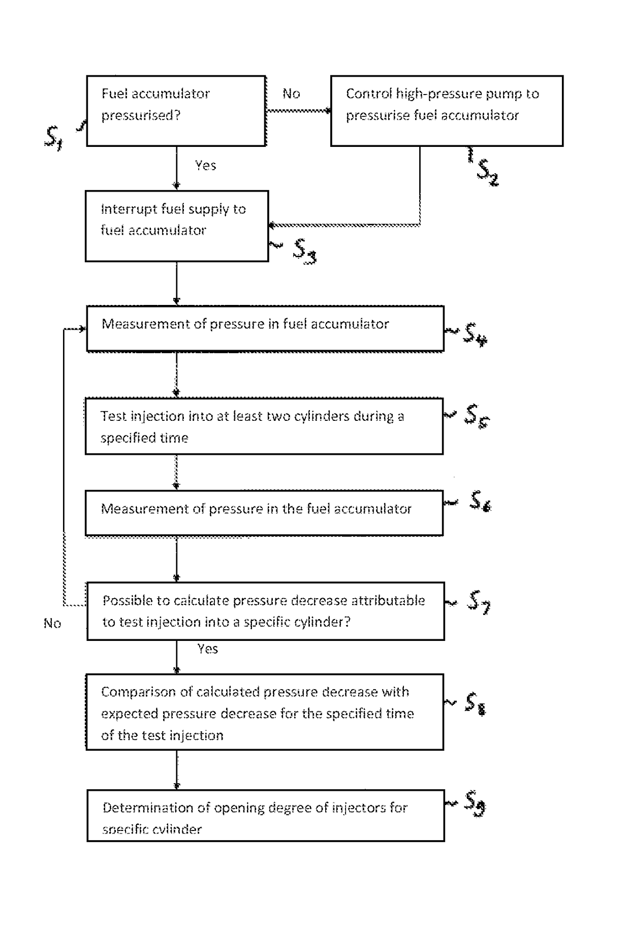
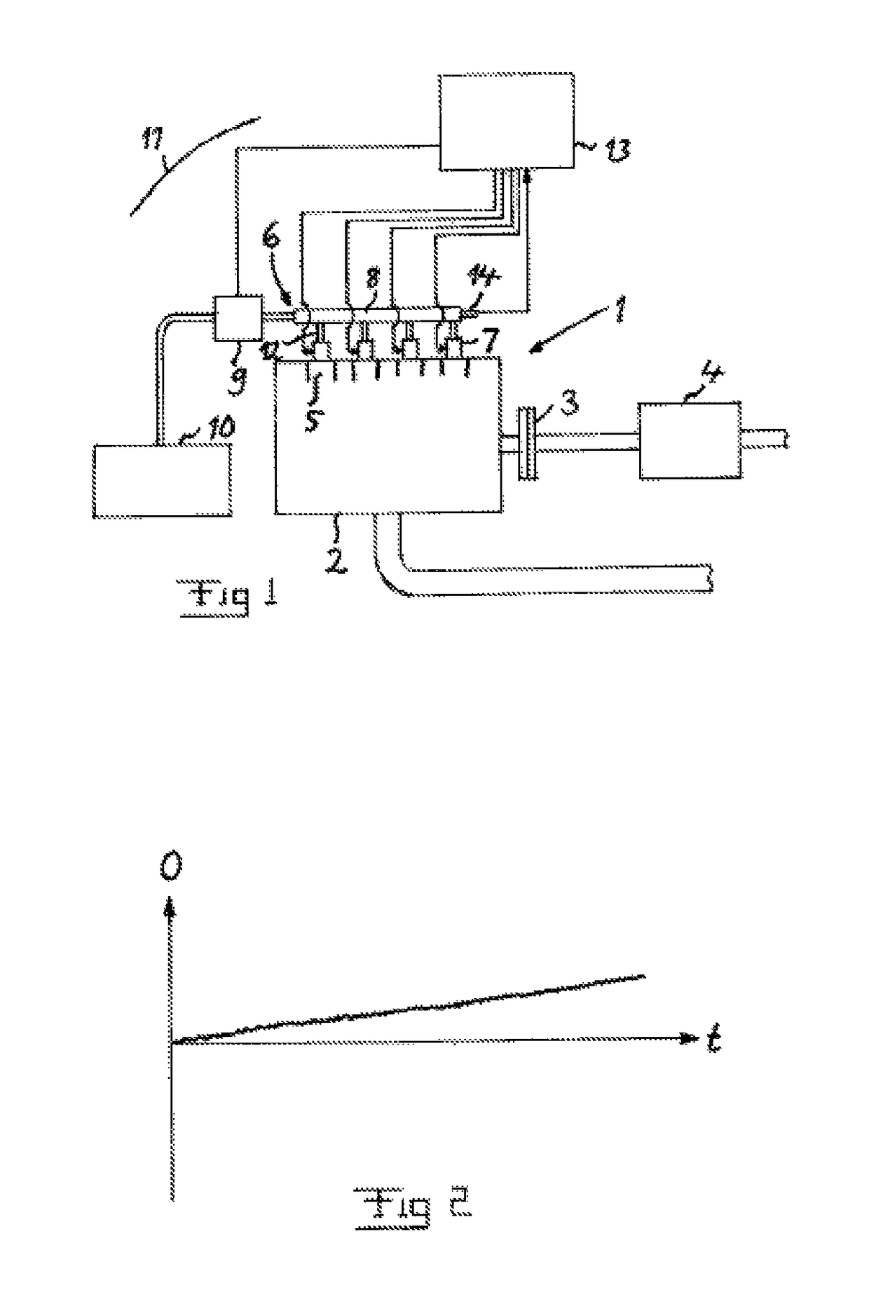
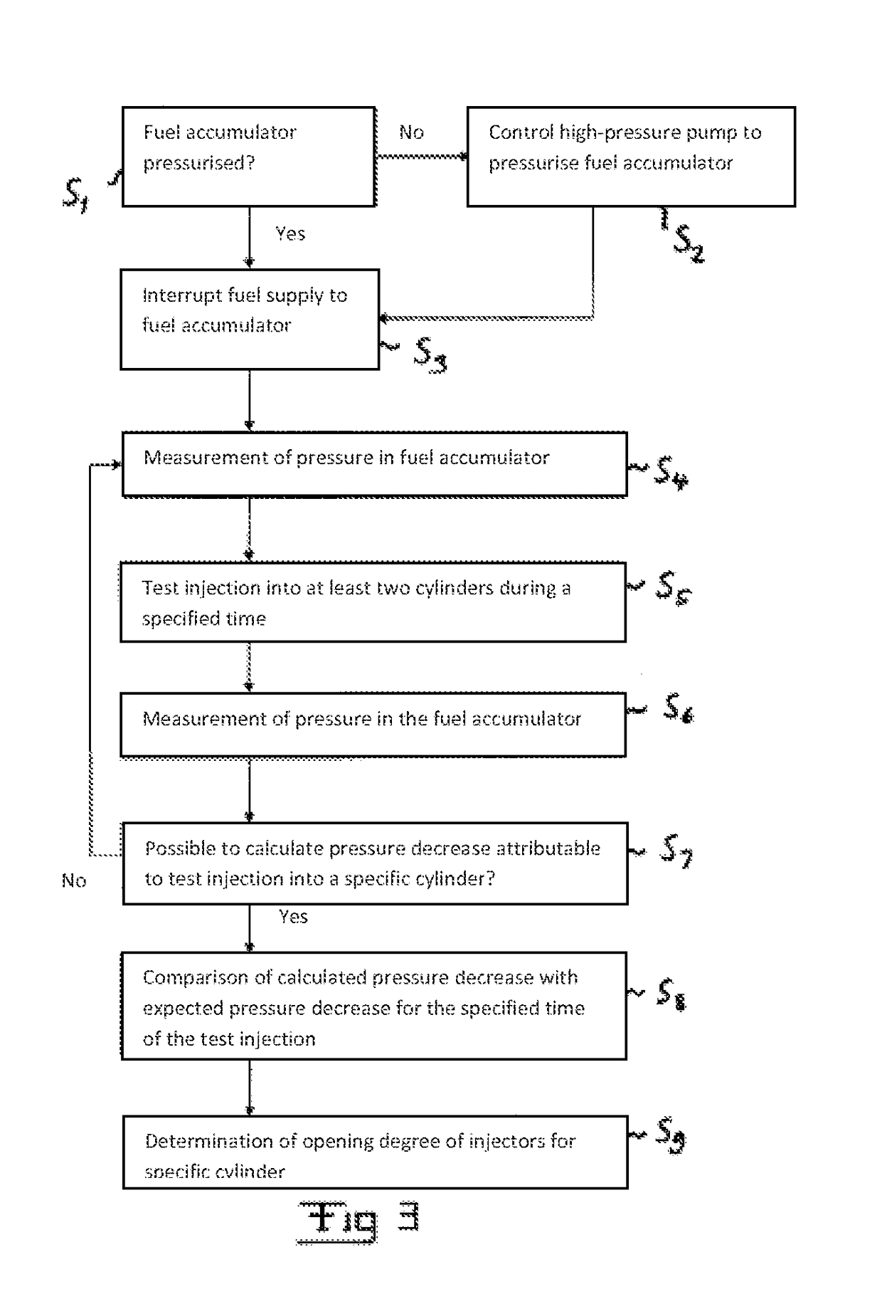
[0024]The use of a combustion engine according to the invention in a motor vehicle will now be described for purposes of exemplifying, and a driveline 1 of a motor vehicle is schematically illustrated in FIG. 1. The driveline 1 comprises a combustion engine 2, e.g. a diesel engine, which is connected to driving wheels (not displayed) of the vehicle via a clutch 3 and a gearbox 4.

[0025]The combustion engine 2 comprises several, specifically four, schematically indicated cylinders 5. It is pointed out, however, that the combustion engine may comprise any suitable number of cylinders, larger than two. Fuel is supplied to the cylinders with the help of a common rail fuel injection system 6. Such fuel injection system 6 comprises a number of electrically controlled injectors 7. Each cylinder of the combustion engine 2 is assigned its own injector 7. The injectors 7 are connected to a fuel accumulator 8 in the form of a so-called common rail, which consists of an accumulator for accumulat...


PUM


Abstract

A method is disclosed to determine the opening degree of injectors in cylinders of a combustion engine, where the combustion engine has at least three cylinders. The injectors are connected to a fuel accumulator in a common rail fuel injection system; the fuel supply to the fuel accumulator is interrupted; and subsequently a test injection of fuel is carried out into at least two and, at most, all but for one cylinder at a time, in different combinations, at such a time that the injection does not cause any combustion in the cylinders. The pressure decreases caused in connection with the different test injections are measured, and the pressure decrease that is attributable to at least one specific injector is calculated based thereupon, which is, in turn, used in the determination of the injector's opening degree.

Description

CROSS-REFERENCE TO RELATED APPLICATIONS[0001]This application claims is a national stage application (filed under 35 U.S.C. 371) of PCT / SE2014 / 050692, filed Jun. 10, 2014 of the same title, which, in turn, claims priority to Swedish Application No. 1350867-6, filed Jul. 11, 2013 of the same title; the contents of each of which are hereby incorporated by reference.TECHNICAL FIELD OF THE INVENTION[0002]The present invention pertains to a method for determining the opening degree of injectors in cylinders in a combustion engine with at least three cylinders, wherein said injectors are connected to a fuel accumulator in a common rail fuel injection system, and wherein the method is started when the fuel accumulator is pressurized, and a combustion engine employing the method.BACKGROUND[0003]The injectors in a said combustion engine are controlled with the help of an engine control device, which controls the opening times for each individual injector in order thus to control the amount o...

Claims


Application Information

Patent Timeline
Patent Type & Authority Patents(United States)
IPC IPC(8): G01M15/00F02M65/00F02D41/24F02D41/38F02D41/22F02D41/26F02M63/02F02D41/00F02D41/04
CPCF02M65/001F02D41/221F02D41/2467F02D41/263F02D41/3809F02D41/3845F02M65/003F02M63/0225F02D2200/0616F02D41/0087F02D41/042F02D2041/224F02D2041/389F02D2200/0602F02D41/401F02M65/005
Inventor BJUREFORS, DANIEL
Owner SCANIA CV AB
Why Eureka
Try Eureka