Method for spectrum sensing unoccupied frequency

a spectrum sensing and unoccupied frequency technology, applied in the field of multi-antenna-based spectrum sensing solutions, can solve the problems of difficulty in differentiation between interference and noise, pre-existing fixed spectrum assignment policies have become less efficient, and energy detector-based spectrum sensing faces challenges

Active Publication Date: 2020-12-29
KING ABDULAZIZ UNIV
View PDF4 Cites 7 Cited by
  • Summary
  • Abstract
  • Description
  • Claims
  • Application Information

AI Technical Summary

Problems solved by technology

However, pre-existing fixed spectrum assignment policies have become less efficient due to wastage of unutilized spectrum when primary users are inactive or silent.
However, energy detector based spectrum sensing faces challenges in selection of the threshold for PU detection, difficulty in differentiation between interference and noise, and poor performance at low signal-to-noise-ratio as described in Tang, H., “Some physical layer issues of wide-band cognitive radio systems,” in Proc.
However, in terms of its impact on the CRN performance, all sources of co-channel interference are equally harmful.
While out-band spectrum sensing can be handled using a separate radio frequency unit, in-band sensing cannot be performed—using the conventional sensing methods—except when the CRN terminal is not engaged in a transmit / receive process, i.e., only when the terminal is in a Quiet Period (QP).
However, since this period is consuming a valuable communication time, it is essential for the CRN terminal to minimize its duration as much as possible.
However, this approach, known as partial spectrum sensing, lowers the throughput as well as complicates the in-band sensing stage.
Each of the aforementioned spectrum sensing and capacity allocation techniques suffers from one or more drawbacks hindering their adoption.

Method used


Image

  • Method for spectrum sensing unoccupied frequency
  • Method for spectrum sensing unoccupied frequency
  • Method for spectrum sensing unoccupied frequency

Examples


Embodiment Construction

[0028]In the drawings, like reference numerals designate identical or corresponding parts throughout the several views. Further, as used herein, the words “a,”“an” and the like generally carry a meaning of “one or more,” unless stated otherwise. The drawings are generally drawn to scale unless specified otherwise or illustrating schematic structures or flowcharts.

[0029]Furthermore, the terms “approximately,”“approximate,”“about,” and similar terms generally refer to ranges that include the identified value within a margin of 20%, 10%, or preferably 5%, and any values therebetween.

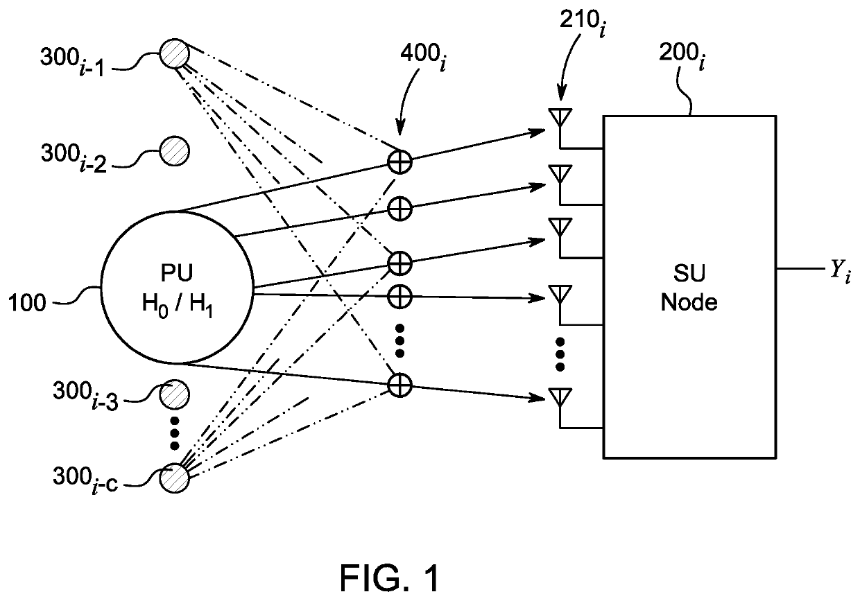
[0030]Most conventional spectrum sensing techniques assume only additive noise and ignore the effect of co-channel interference. Moreover, in deriving the probability of detection and probability of false alarm, a Gaussian assumption is employed for the received statistics at each node of a cognitive radio network. However, such an assumption is not always true in real practice.

[0031]To address these issues...


PUM


Abstract

A method for spectrum sensing for cognitive radio includes performing a process of local spectrum sensing using receive beamforming and energy detection at each of a plurality of secondary users included in a cognitive radio network, wherein the process of local spectrum sensing decides between two hypotheses corresponding to absence and presence of a primary user, the two hypotheses being formulated using a primary user signal, a plurality of co-channel interferences, and sensing noise, the primary user signal, the plurality of co-channel interferences, and the sensing noise being received at each of the plurality of secondary users, and a set of beamforming weights of the receive beamforming is determined by optimizing a probability of detection and constraining a probability of false alarm.

Description

CROSS-REFERENCE TO RELATED APPLICATIONS[0001]The present application is a Continuation of Ser. No. 16 / 869,796, pending, having a filing date of May 8, 2020.BACKGROUNDTechnical Field[0002]The present disclosure relates to a multiple antenna-based spectrum sensing solution for cognitive radio.Description of Related Art[0003]The “background” description provided herein is for the purpose of generally presenting the context of the disclosure. Work of the presently named inventors, to the extent it is described in this background section, as well as aspects of the description which may not otherwise qualify as prior art at the time of filing, are neither expressly or impliedly admitted as prior art against the present invention.[0004]Due to the rapid growth in wireless communication, the demand for spectrum segments is increasing. However, pre-existing fixed spectrum assignment policies have become less efficient due to wastage of unutilized spectrum when primary users are inactive or si...

Claims


Application Information

Patent Timeline
Patent Type & Authority Patents(United States)
IPC IPC(8): H04W16/14H04B7/08H04W24/08H04B17/382H04L27/00
CPCH04L27/0006H04B7/0897H04B17/382H04W24/08H04W16/14H04B7/086H04B17/23
Inventor MOINUDDIN, MUHAMMEDAL-SAGGAF, UBAID M.ALREFAEI, MOHAMMED A.AHMAD, JAWWAD
Owner KING ABDULAZIZ UNIV
Why Eureka
Try Eureka