System and method for noise reduction in magnetic resonance imaging

a magnetic resonance imaging and noise reduction technology, applied in the field of magnetic resonance imaging system and method for noise reduction, can solve the problems of difficult and often impossible isolation of in-band noise signals, many sources of noise, movement artifacts, etc., and achieve the effect of increasing the total noise entering the receiver, preserving the signal processing chain, and measuring more accurately

Active Publication Date: 2015-03-03
THE JOHNSON REVOCABLE TRUST DATED 6 25 2003
View PDF125 Cites 22 Cited by
  • Summary
  • Abstract
  • Description
  • Claims
  • Application Information

AI Technical Summary

Benefits of technology

[0036]In an alternative preferred embodiment of the invention, the receiver measures the RF signal over a much wider frequency band than that normally required for the MRI signal of interest (less than 100 kHz). For example, the RF signal may be highly oversampled with respect to the MRI signal of interest, with the large bandwidth preserved through the signal processing chain. This will, of course, increase the total noise entering the receiver, which is contrary to the conventional approach. However, let us assume the broadband body noise comprises a time-series of narrow pulses, caused by fast current dipoles, as shown in FIG. 3A. (These broadband noise pulses are quite distinct from the narrowband MRI excitation pulses.) Then these pulses can be detected and rejected from the signal using digital processing as shown schematically in FIG. 4, enabling the weaker narrow-band signal of interest to be measured more accurately. This can be accomplished, for example, by using a single pickup coil, which does not filter or and broaden the pulses.
[0037]These noise pulses may not all have the same amplitude, or polarity, or spectral characteristics, or emanate from the same location, and may even overlap to some degree, Practically, fast real-time processing may enable these to be identified and subtracted without requiring inordinate amounts of storage. Further pulse discrimination may be obtained using a plurality of pickup coils in different locations, each with its own digital receiver. Since the current dipoles may be localized, the relative pulse-heights may permit further correlation, enabling further noise cancelation.
[0060]A further object comprises providing an imaging method, comprising: generating an atomic nucleus-orienting magnetic field; sensing outputs of at least one antenna comprising a signal corresponding to a precession of nuclei within the magnetic field in response to the generated magnetic field and an interfering component over time; digitally processing the sensed outputs in a manner sensitive to a time correlation of the signal corresponding to a precession of nuclei within the magnetic field and the interfering component over time, at a rate oversampled with respect to a Nyquist rate of the interfering component; and generating an image corresponding to a spatial origin of the signal corresponding to a precession of nuclei within the magnetic field with algorithmically reduced contribution of the interfering signal.

Problems solved by technology

There may be many sources of noise, including noise associated with electrical currents in the antenna and amplifiers in the receiver.
The dominant source of noise in MRI systems typically comprises fluctuating Johnson noise associated with thermally excited eddy currents in the electrically conducting medium of the human body or other object under examination.
However, performing an integration over the coherence time to maximize the signal to noise ratio may unduly prolong an MRI scan, which is uncomfortable to the patient, and may lead to movement artifacts during the scan.
The isolation of the signal with respect to in-band noise is difficult and often impossible, leading to impaired resolution or aberrations, longer scan time, and / or image noise.
Such an improvement is significant but limited.
However, in many cases the receiver noise is already less than the body noise, so that very little additional SNR is obtained from further reduction in receiver noise.
The prior art has not effectively solved the issue of noise in bioelectric and / or biomagnetic field measurements, such as the background body noise in MRI systems, so that one may obtain high-resolution images with ultra-sensitive receivers, without requiring the largest magnetic fields and long integration times.

Method used


Image

  • System and method for noise reduction in magnetic resonance imaging
  • System and method for noise reduction in magnetic resonance imaging
  • System and method for noise reduction in magnetic resonance imaging

Examples


Embodiment Construction

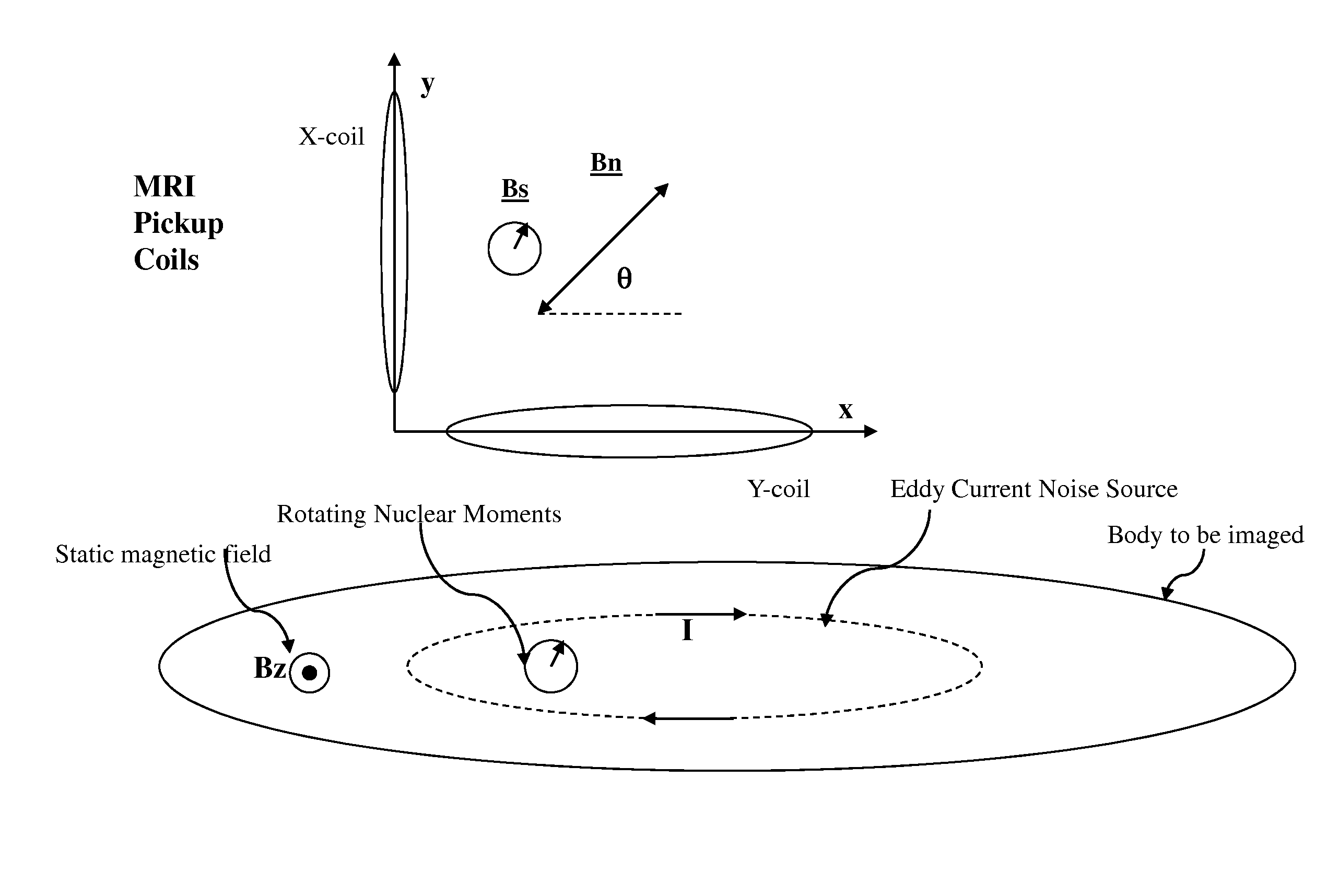
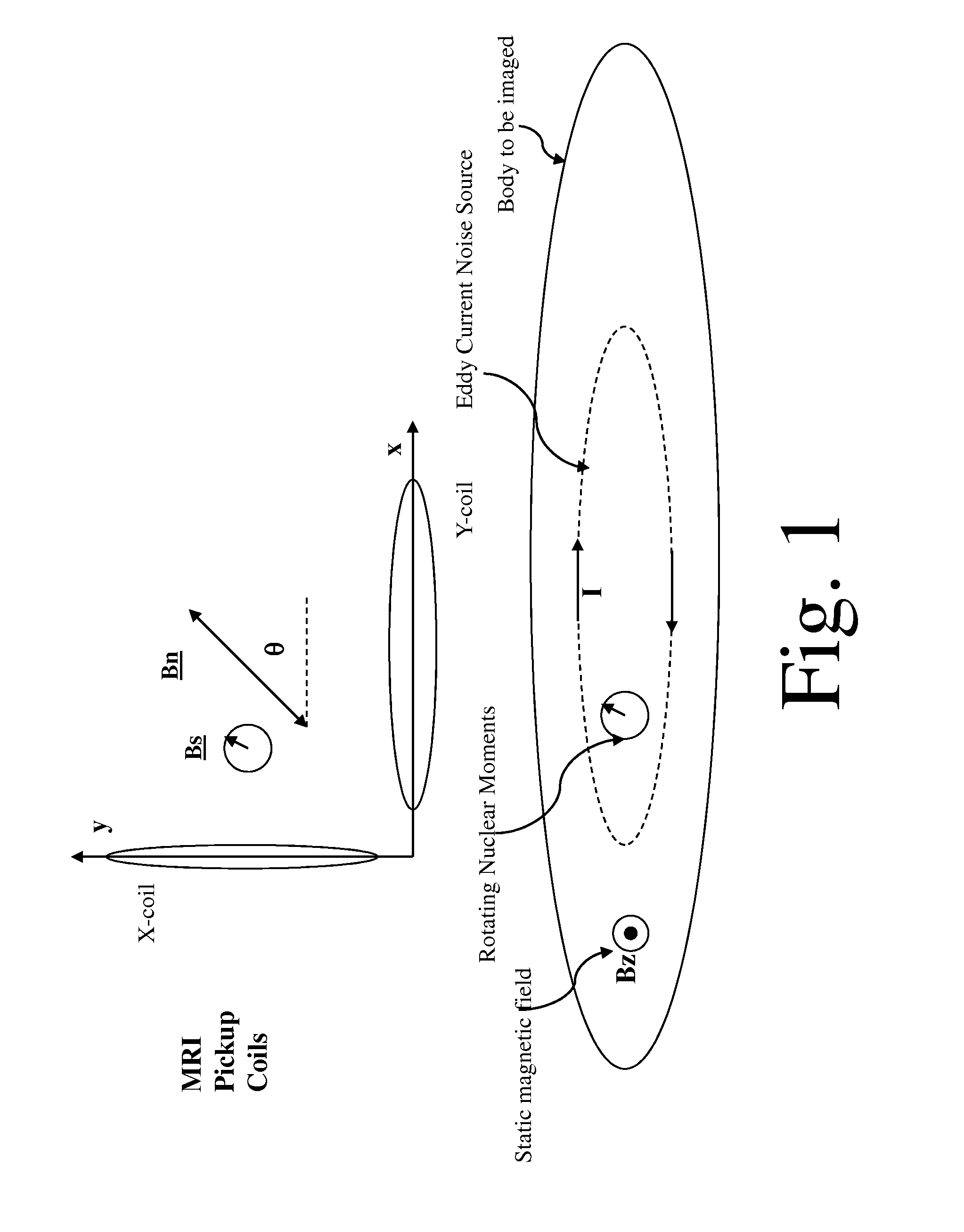
[0069]In classic MRI, as shown in FIG. 1, a large static uniform magnetic field is applied in the z-direction, in order to polarize the magnetic nuclei in the object to be imaged (usually a part of a human body) along the z-axis. An RF transmit coil applies an RF field that causes the nuclei to rotate (precess) around the z-axis, generating RF magnetic fields that rotate in the x-y plane at the Larmor frequency. Small quasi-static magnetic field gradients are applied that shift this frequency slightly, depending on position. A coil placed near the body (the y-coil in FIG. 1) measures this narrow-band signal, which is subsequently amplified and Fourier-transformed to recover the positional information. In addition to the nuclear resonance signal, broadband fluctuating eddy currents in the body also produce RF magnetic fields in the pickup coil, but for a single current dipole noise source, these noise fields are linearly polarized rather than circularly polarized as for the nuclear m...


PUM


Abstract

Signals of interest in magnetic resonance imaging (MRI) systems comprise narrowband, circularly polarized (CP) radio-frequency magnetic fields from rotating atomic nuclei. Background “body noise” may comprise broadband, linearly polarized (LP) magnetic fields from thermally-activated eddy currents, and may exceed the signal in a band of interest, limiting the imaging resolution and requiring excessive averaging times. Noise may be selectively detected and substantially suppressed, while enhancing the signal of interest, using appropriate digital time-domain algorithms. At least two quadrature receiving antennas may be employed to distinguish and separate the LP noise from the CP signal. At least one broadband receiver may be used to identify and localize fast noise sources and to digitally filter the representation of their radio-frequency magnetic fields in the signal. Selective body noise reduction may allow enhanced signal-to-noise ratio of the system, leading to improved imaging resolution and shorter scan time.

Description

BACKGROUND OF THE INVENTION[0001]Nuclear magnetic resonance (NMR) is associated with coherent resonant rotation of magnetic atomic nuclei, around an axis parallel to a large static applied magnetic field, following excitation by a radio-frequency pulse. The rotation frequency (the Larmor frequency) is proportional to the applied magnetic field, given by f=γβ, where γ=42 MHz / T for the hydrogen nucleus (proton) and of similar magnitude for other nuclei. The coherent decay time, known as T2, is typically of order 100 ms, reflecting the very high-Q nuclear rotations with only weak interactions with the atomic environments. In magnetic resonance imaging (MRI), appropriate weak gradients in applied magnetic field are used to obtain frequency gradients, thus enabling Fourier transforms of the nuclear signal to be mapped onto spatial images. However, the coherent signal is extremely weak, corresponding to radio frequency (RF) magnetic fields (for 1-mm resolution) of order 10−14 T (=10 fT) i...

Claims


Application Information

Patent Timeline
Patent Type & Authority Patents(United States)
IPC IPC(8): G01R33/48G01R33/56
CPCG01R33/56G01R33/3621G01R33/3678G01R33/543G01R33/546G01R33/5608G01R33/56518G01R33/56563
Inventor KADIN, ALAN M.
Owner THE JOHNSON REVOCABLE TRUST DATED 6 25 2003
Why Eureka
Try Eureka