
Positive electrode material and lithium secondary battery using same

a lithium secondary battery and positive electrode technology, applied in the direction of positive electrodes, active material electrodes, cell components, etc., can solve the problems of increasing resistance in the positive electrode, difficulty in high-rate charge and discharge at 2 c or above, etc., to achieve the effect of suppressing the oxidative decomposition of the electrolyte, increasing the structural stability of the positive electrode active material, and reducing the difficulty of self-discharg

Active Publication Date: 2021-01-12
TOYOTA JIDOSHA KK
View PDF10 Cites 0 Cited by
  • Summary
  • Abstract
  • Description
  • Claims
  • Application Information

AI Technical Summary

Benefits of technology

[0005]It is an object of the present invention, arrived at in order to solve the above problem, to provide a positive electrode material that combines both Li ion conductivity and high durability. A related object is to provide a lithium secondary battery with excellent input-output characteristics and durability.
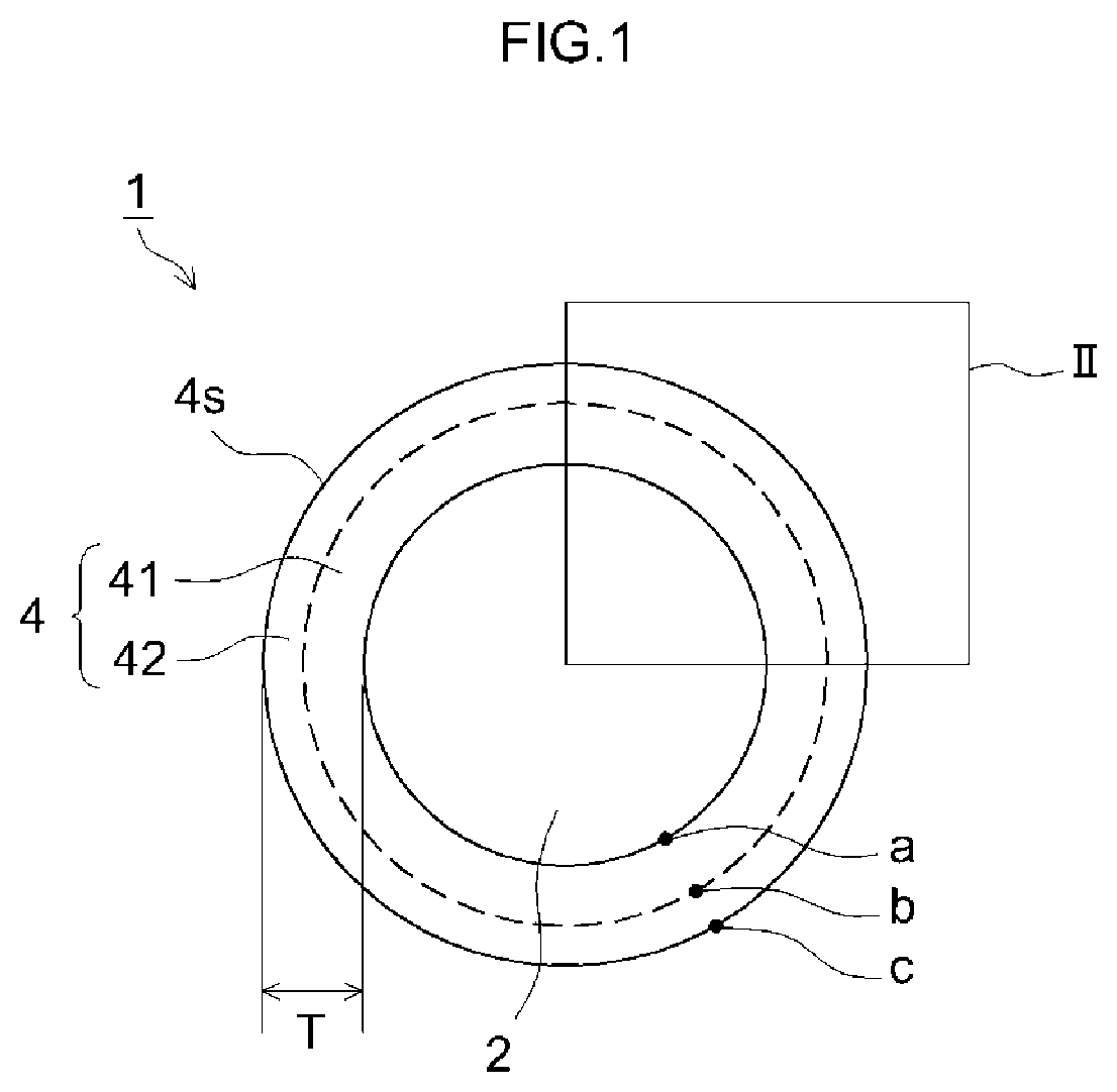
[0007]In the positive electrode material, the concentration of fluorine at a position (Point c) on the surface of the cover is higher than at a position (Point b) in the center of the cover, in the thickness direction. As a result, oxidative decomposition of the electrolyte is suppressed, and self-discharge can be suitably reduced. Further, it becomes possible to increase the structural stability of the positive electrode active material, through suppression of leaching of the constituent elements from the positive electrode active material. In the positive electrode material, moreover, the concentration of lithium is higher at a position (Point a) of the cover in contact with the positive electrode active material than at a position (Point b) in the center of the cover, in the thickness direction. As a result, it becomes possible to increase the Li ion conductivity of the positive electrode active material and to suitably reduce the resistance of the positive electrode. Therefore, using a positive electrode material having the above configuration allows realizing a lithium secondary battery boasting an excellent balance between input-output characteristics and durability, as compared with a case where for instance there is used the positive electrode active material disclosed in Japanese Laid-Open Patent Publication No. 2000-128539.
[0008]In one embodiment of the positive electrode material disclosed herein, the cover has a Li concentration gradient such that Li concentration decreases from the side near the positive electrode active material towards the surface. As a result, intercalation / deintercalation of Li in the positive electrode active material becomes smoother, and battery resistance can be reduced yet more suitably. It becomes therefore possible to further increase high input-output characteristics.
[0009]In one embodiment of the positive electrode material disclosed herein, the cover has a F concentration gradient such that F concentration increases from the side near the positive electrode active material towards the surface. As a result, it becomes possible to reduce more suitably oxidative decomposition of an electrolyte and leaching of constituent elements from the positive electrode active material. Durability can be further enhanced as a result.
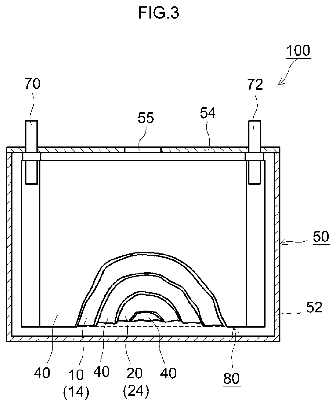
[0010]In another aspect, the present invention provides a lithium secondary battery provided with the above positive electrode material. Such a lithium secondary battery exhibits for instance low initial resistance and high durability such that battery capacity does not drop readily even when the battery is stored over long periods of time in a high-voltage state.

Problems solved by technology

As a result, a problem arose in that resistance in the positive electrode increased and for example high-rate charge and discharge at 2 C or above became difficult.

Method used


Image

  • Positive electrode material and lithium secondary battery using same
  • Positive electrode material and lithium secondary battery using same
  • Positive electrode material and lithium secondary battery using same

Examples


example 1

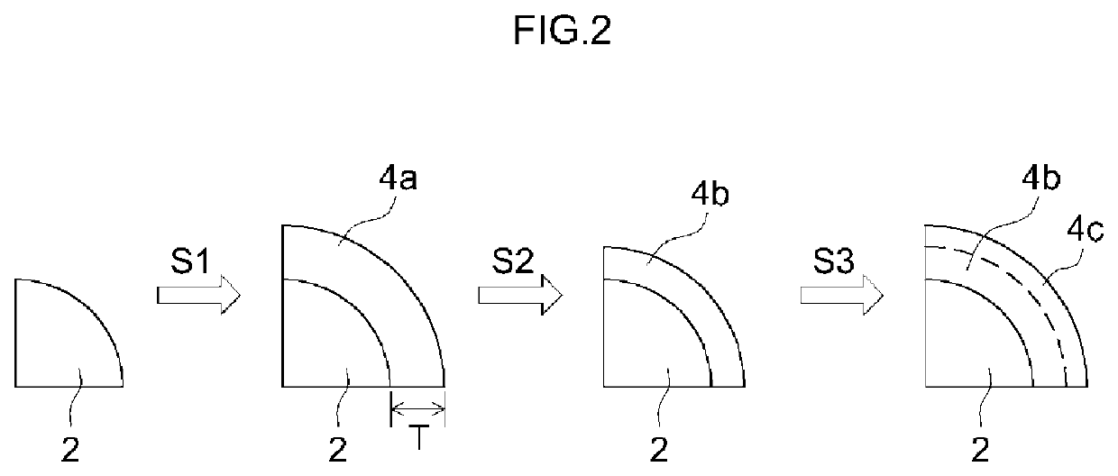
[0080]Firstly a particulate lithium-nickel-cobalt-manganese complex oxide (layered structure; LiNi0.33Co0.33Mn0.33O2) having an average particle size of 10 μm was prepared as a positive electrode active material (step S0). A sputtering target of Al was used next to sputter Al onto the surface of the positive electrode active material particles, while the positive electrode active material particles were being rotated. Herein DC current was used for sputtering, and the film formation rate was set to 0.1 nm / h. As a result, an Al layer was formed on the surface of the positive electrode active material particles (step S1). Next the positive electrode active material particles with Al layer were thermally treated at 300° C. for 12 hours. As a result, Li was caused to diffuse into the Al layer, to thereby form a Li enriched layer (step S2). Next a 5 mass % hydrofluoric acid aqueous solution was prepared, and the positive electrode active material particles with Li enriched layer were sub...

examples 2 and 3

, Comparative Examples 2 to 6

[0081]In Comparative example 2 a positive electrode material was obtained in the same way as in Example 1, but herein the duration of the thermal treatment in the step S2 was shortened and the duration of the fluorination treatment in the step S3 was likewise shortened. In Comparative example 3 a positive electrode material was obtained in the same way as in Example 1, but herein the duration of the fluorination treatment in the step S3 was shortened. In Comparative example 4 a positive electrode material was obtained in the same way as in Example 1, but herein the duration of the thermal treatment in the step S2 was shortened. In Example 2 a positive electrode material was obtained in the same way as in Example 1, but herein the duration of the thermal treatment in the step S2 was lengthened. In Comparative example 5 a positive electrode material was obtained in the same way as in Example 2, but herein the duration of the thermal treatment in the step S...

examples 4 to 10

[0082]In Examples 4 to 6 respective positive electrode materials were obtained in the same way as in Example 1, but modifying herein the sputtering time and the Al coverage of the step S1. In Examples 7 to 10 positive electrode materials were obtained in the same way as in Example 1 but herein Ti, Zr, Nb and Ta were used as a sputtering target, respectively, instead of Al in the step S1.

[0083]Evaluation of the Positive Electrode Material by XPS.

[0084]The thickness (nm) of the cover of the obtained positive electrode materials, and the coverage (atomic %) of the positive electrode active material surface were measured by XPS. The coverage was calculated on the basis of the following expression, with a coverage element being X: element ratio of X / (element ratio of X+element ratio of Ni+element ratio of Mn+element ratio of Co)×100. The results are given in Table 1.

[0085]Each obtained positive electrode material was analyzed by XPS for the Point a in contact with the positive electrode ...


PUM

PropertyMeasurementUnit
particle sizeaaaaaaaaaa

Abstract

The present invention provides a positive electrode material for lithium secondary batteries, having: a positive electrode active material containing Li; and a cover disposed on the positive electrode active material, and containing Li and F, and further containing one or two or more cover elements from among Al, Ti, Zr, Ta and Nb. With a Point a as an arbitrary point of the cover in contact with the positive electrode active material, a Point c as a point on the surface of the cover at a shortest distance from the Point a, and a Point b as a midpoint between the Point a and the Point c, an analysis of the Point a, the Point b and the Point c by X-ray photoelectron spectroscopy yields a ratio of Li concentration at the Point a with respect to the Li concentration at the Point b is 1.1 or higher and lower than 10.8, and a ratio of F concentration at the Point c with respect to F concentration at the Point b is 1.1 or higher and lower than 51.1.

Description

CROSS REFERENCE TO RELATED APPLICATIONS[0001]The present application claims priority based on Japanese Patent Application No. 2017-181966, filed on Sep. 22, 2017, the entire contents whereof are incorporated in the present description by reference.BACKGROUND OF THE DISCLOSURE1. Field[0002]The present invention relates to a positive electrode material and a lithium secondary battery using the positive electrode material.2. Background[0003]Further improvement of energy density and durability in lithium secondary batteries is being addressed as one factor of performance improvement. In this context, Japanese Laid-Open Patent Publication No. 2000-128539, Japanese Laid-Open Patent Publication No. 2015-529943, Japanese Laid-Open Patent Publication No. 2017-107827, and Japanese Laid-Open Patent Publication No. 2017-084673 disclose positive electrode materials obtained by subjecting a positive electrode active material to a surface treatment. For instance, Japanese Laid-Open Patent Publicat...

Claims


Application Information

Patent Timeline
Patent Type & Authority Patents(United States)
IPC IPC(8): H01M4/36H01M10/0525H01M4/505H01M4/525H01M4/38H01M10/052H01M4/02
CPCH01M4/366H01M4/382H01M4/505H01M4/525H01M10/0525H01M10/052H01M2004/028H01M4/628H01M10/4235H01M2004/021Y02E60/10
Inventor GOTO, IPPEI
Owner TOYOTA JIDOSHA KK
Learn More