Fastening device for a trampoline

a technology for fastening devices and trampoline, which is applied in the direction of fastening means, sheet joining, sport apparatus, etc., can solve the problems of steel springs giving rise to disturbing squeaking noises, steel springs based suspension arrangements,

Active Publication Date: 2021-01-26
ANGEHRN AG UMFORMTECHN
View PDF14 Cites 1 Cited by
  • Summary
  • Abstract
  • Description
  • Claims
  • Application Information

AI Technical Summary

Benefits of technology

[0013]The invention is based inter alia on the realization that a transition portion which moves away laterally is advantageous for the design of the cord hook. In particular, in this way, it is possible to avoid transverse forces on the cord hook that tilt the hook during intended use.
[0058]According to a further aspect of the present invention, which may be used independently of but advantageously with the aspects described above, the cord hooks are designed such that the at least one band element can be mounted manually. This may for example be achieved by virtue of the securing portion of the corresponding cord hook having at least one outwardly or inwardly open hook element. It is self-evidently also conceivable for the corresponding securing portion to have two hook elements which are in each case outwardly or inwardly open. It is furthermore conceivable, instead of the hook elements, to use a bolt element which can be releasably mounted in the cord hooks. The band element is then looped around the bolt element before the bolt element is introduced into the cord hooks. By means of this possibility for mounting both the loop and the at least one band element, it is possible for a single defective cord hook to be easily exchanged even after the trampoline has been fully assembled. Furthermore, the mounting after the securing of the band elements is advantageous in terms of the production process, because the intermediate product composed of jump mat and band elements secured thereto is easier to handle, for example easier to stack, without cord hooks hanging therefrom.

Problems solved by technology

Steel-spring-based suspension arrangements however have the disadvantage that they tension the jump mat so as to be very taut.
Furthermore, the steel springs give rise to disturbing squeaking noises during the use of the trampoline.
When training on devices with such a suspension arrangement of the jump mat, joints and the spinal column are therefore subjected to considerable loads.
The fourth cord portion has the above-described sausage-shaped bracket assembly, which disadvantageously reduces the active tension section thereof.
This firstly influences the oscillation quality, because it is not possible for the entire stretching potential of the rubber to be utilized uniformly for generating the oscillation.
Secondly, the overstretching, which occurs earlier, of the fourth cord portion leads to faster stress aging, as a result of which the cord loop must be prematurely exchanged.

Method used


Image

  • Fastening device for a trampoline
  • Fastening device for a trampoline
  • Fastening device for a trampoline

Examples


first embodiment

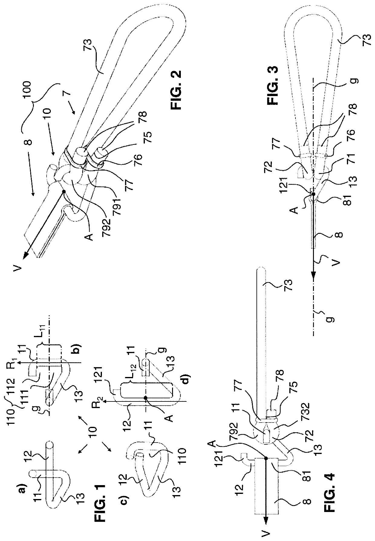
[0079]FIG. 1 is divided into four sub-figures a) to d) and shows the cord hook 10. The cord hook 10 is formed in one piece from one wire piece. The cord hook 10 comprises a receiving portion 11, a securing portion 12 arranged transversely with respect thereto and spaced apart therefrom, and a transition portion 13, which connects the receiving portion 11 and the securing portion 12 to one another.

[0080]Sub-FIG. 1a) shows the cord hook 10 in a front view. The view is thus directed from the distal direction toward the receiving portion 11 and the securing portion 12 situated therebehind. In sub-FIG. 1b), the view is directed in a second direction R2 of the securing portion 12. In sub-FIG. 1c), the view is directed perspectively from above toward the cord hook 10, and in sub-FIG. 1d), the view is directed from above toward the cord hook 10 counter to a first direction R1 (see sub-FIG. 1b).

[0081]As illustrated in FIGS. 1a)-d), cord hook 10 is composed of a receiving portion 11 which run...

second embodiment

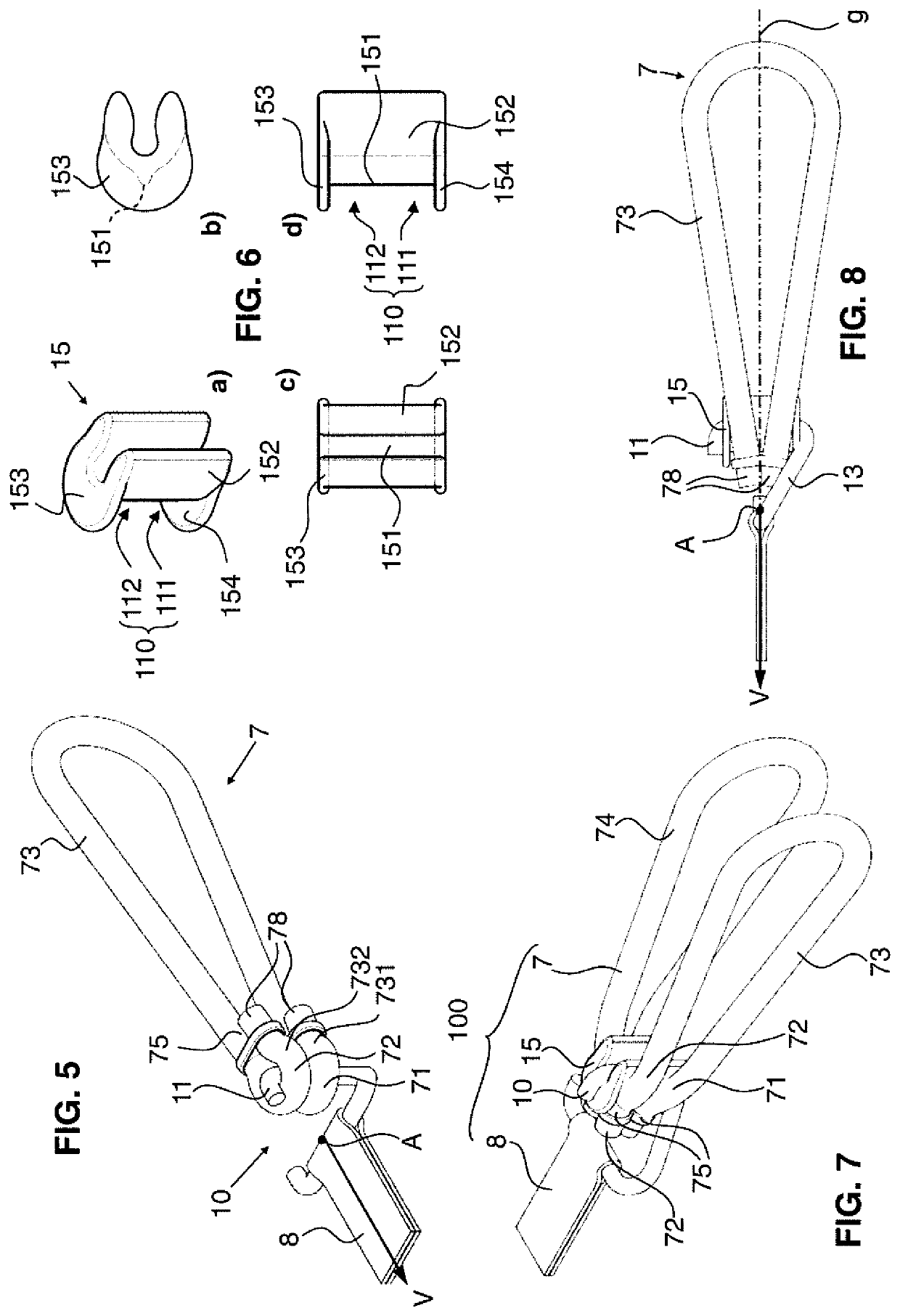
[0098]FIGS. 7-10 illustrate an alternative embodiment of the securing system 100. Firstly, the wire hook 10 as per FIG. 1 is shown, which is refined with the additional sleeve 15 as per FIG. 6. the loop 7 is also illustrated.

[0099]The loop 7 as per the second embodiment has a first receiving portion 73 and additionally a second cord portion 74. The loop 7 is thus formed from two cord portions. The first cord portion 73 again has the first and second end portions 731, 732. The second cord portion 74 likewise has a first end portion 741 and a second end portion 742.

[0100]The loop 7 as per the second embodiment is now produced by virtue of the first cord portion 73 and the second cord portion 74 being laid parallel and adjacent to one another, such that firstly the first end portion 731 of the first cord portion 73 and the second end portion 742 of the second cord portion 74 make contact, and secondly also the second end portion 732 of the first cord portion 73 and the first end portio...

fifth embodiment

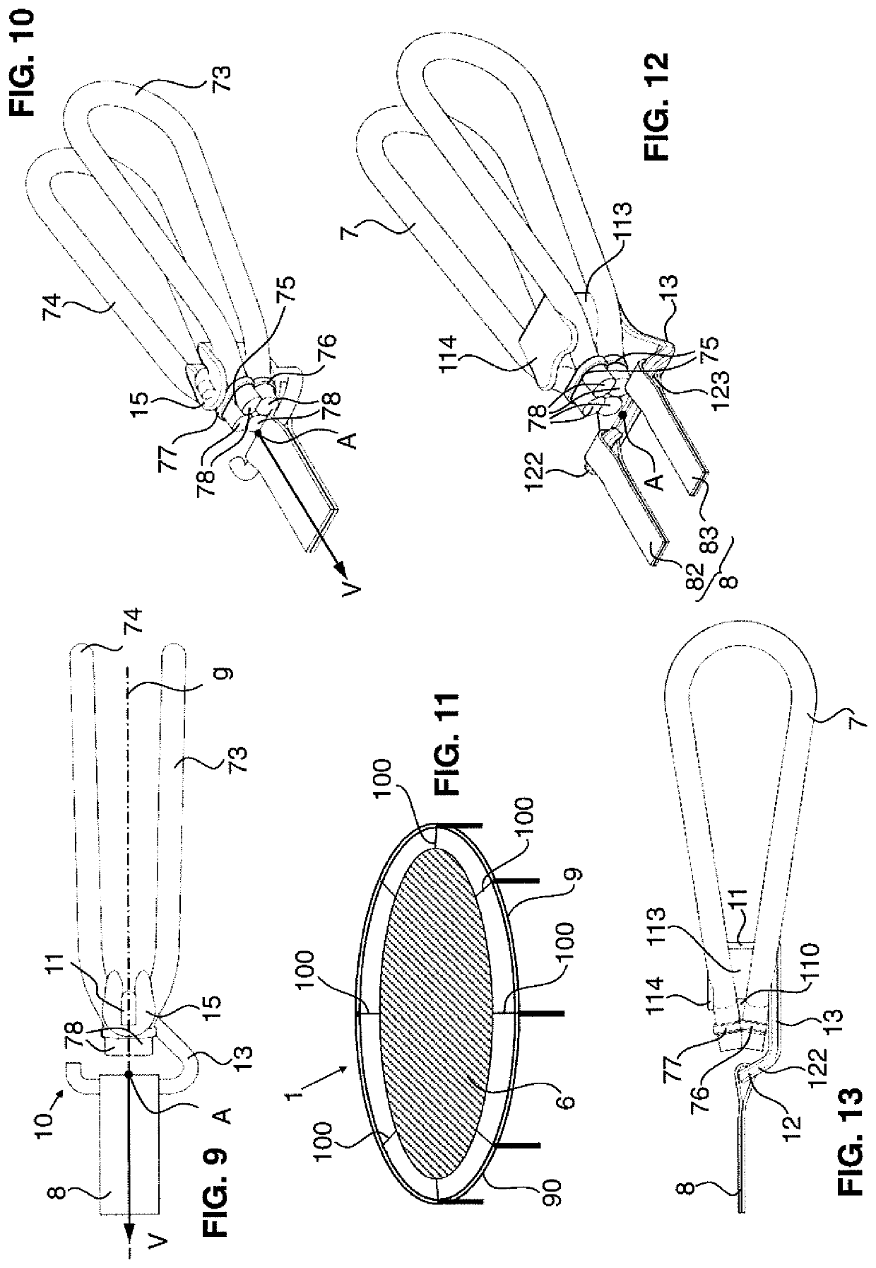
[0120]FIG. 29 shows the again drum-like main body 113, which is of U-shaped cross section, of the cord hook 10, which main body extends with its longitudinal axis along the first direction R1. At the end side in relation to the first direction R1, the main body 113 is closed off by means of a plate-like covering 114 which projects toward the securing element 12. The plate-like covering covers the main body 113 to both sides and in the proximal direction, that is to say toward the securing portion 12. The covering 114 is again, as described in the context of the fifth embodiment, arranged so as to be inclined toward the action point A. As can be seen in FIGS. 30, 32, this permits areal contact between the second loop end portion 72 mounted in the receiving portion 11 and that surface of the covering 114 which is directed toward the cord hook 10.

[0121]The optimum inclination of the covering 114 is thus dependent on the diameter of the trampoline frame 9, on the length of the loop 7, a...


PUM


Abstract

A cord hook for fastening a jump mat to a trampoline frame includes a holding section for holding a first and a second loop end section of the cord loop and a fastening section for fastening the flexible band element, wherein a main tension vector (V) is defined by tension at the band element. The hook has a transition section connecting the holding section and the fastening section and is designed in such a way that a straight line (g) through the main tension vector (V) divides the holding space into a first partial space and a second partial space in such a way that, when the cord hook is used as intended, the first loop end section lies in the first partial space and the second loop end section lies in the second partial space. Also disclosed are a trampoline and a method for fastening the jump mat.

Description

TECHNICAL FIELD[0001]The present invention is concerned with a cord hook of a securing device for a trampoline, with a securing device of said type for the insertion of a jump mat of the trampoline into the frame device of the trampoline.PRIOR ART[0002]Trampolines, or mini trampolines, which are used for the promotion of health and for therapy purposes, require a suitable securing system, which is capable of oscillating, for the securing and tensioning or mounting of the jump mat.[0003]It is known for the jump mat to be secured in frame devices of mini trampolines using steel springs. Steel-spring-based suspension arrangements however have the disadvantage that they tension the jump mat so as to be very taut. Furthermore, the steel springs give rise to disturbing squeaking noises during the use of the trampoline. When swinging or lightly jumping on steel-spring mini trampolines, a sinking depth to which the person exercising sinks into the mat amounts to just 20 millimeters to 60 mi...

Claims


Application Information

Patent Timeline
Patent Type & Authority Patents(United States)
IPC IPC(8): A63B5/11F16B5/06A63B21/055F16B45/00
CPCA63B5/11A63B21/0557F16B5/0692A63B21/0552F16B45/00F16B45/012
Inventor BISANG, ERWINDURRER-KUETTEL, LUDWIGMEHR, CHRISTIANSCHWARZ, SILVAN
Owner ANGEHRN AG UMFORMTECHN
Why Eureka
Try Eureka