Illuminant

a technology of illumination and backlighting, applied in the field of illumination, can solve the problems of not wanting to have information displayed and/or marked permanently, affecting the function of the respective product, and/or having a disadvantageous effect on the aesthetics/appearance of the product, and achieve the effect of low cost and simple means

Active Publication Date: 2021-01-26
SINGULUS TECHNOLGIES AG
View PDF43 Cites 0 Cited by
  • Summary
  • Abstract
  • Description
  • Claims
  • Application Information

AI Technical Summary

Benefits of technology

[0017]On the one hand, the connecting layer serves for connecting the metallic, translucent layer with the transparent substrate layer. Preferably, the side of the connecting layer facing the metallic, translucent layer is formed in a planar manner in order to simplify the coating with the metallic, translucent layer and / or improve the homogeneity of the metallic, translucent layer. On the other hand, the connecting layer serves for compensating any unevenness caused by the decoupling structures in the transparent substrate layer, as will be explained in more detail below.
[0035]The present disclosure provides an improved illuminant that can be produced with simple means and at low cost, satisfies the highest expectations with respect to aesthetics, and offers a range of new functions by being able to display information with the help of light on the one hand and achieving a homogeneous and, depending on the field of application, reflective appearance under daylight conditions on the other hand.

Problems solved by technology

In many cases, however, it is not desired to have information displayed and / or marked permanently (e.g., under daylight conditions).
Then, however, the means by which luminous information is displayed are usually still visible or discernible, which may impair the function of the respective product and / or have a disadvantageous effect on its aesthetics / appearance.
Such display symbols are, however, visible under daylight conditions so that the viewer or user of the backlit plastic component does not get a homogeneous impression of the metallic layer.

Method used


Image

  • Illuminant
  • Illuminant
  • Illuminant

Examples


Embodiment Construction

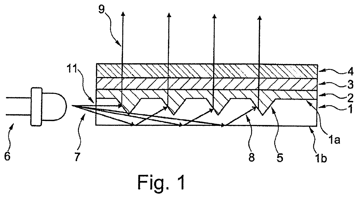
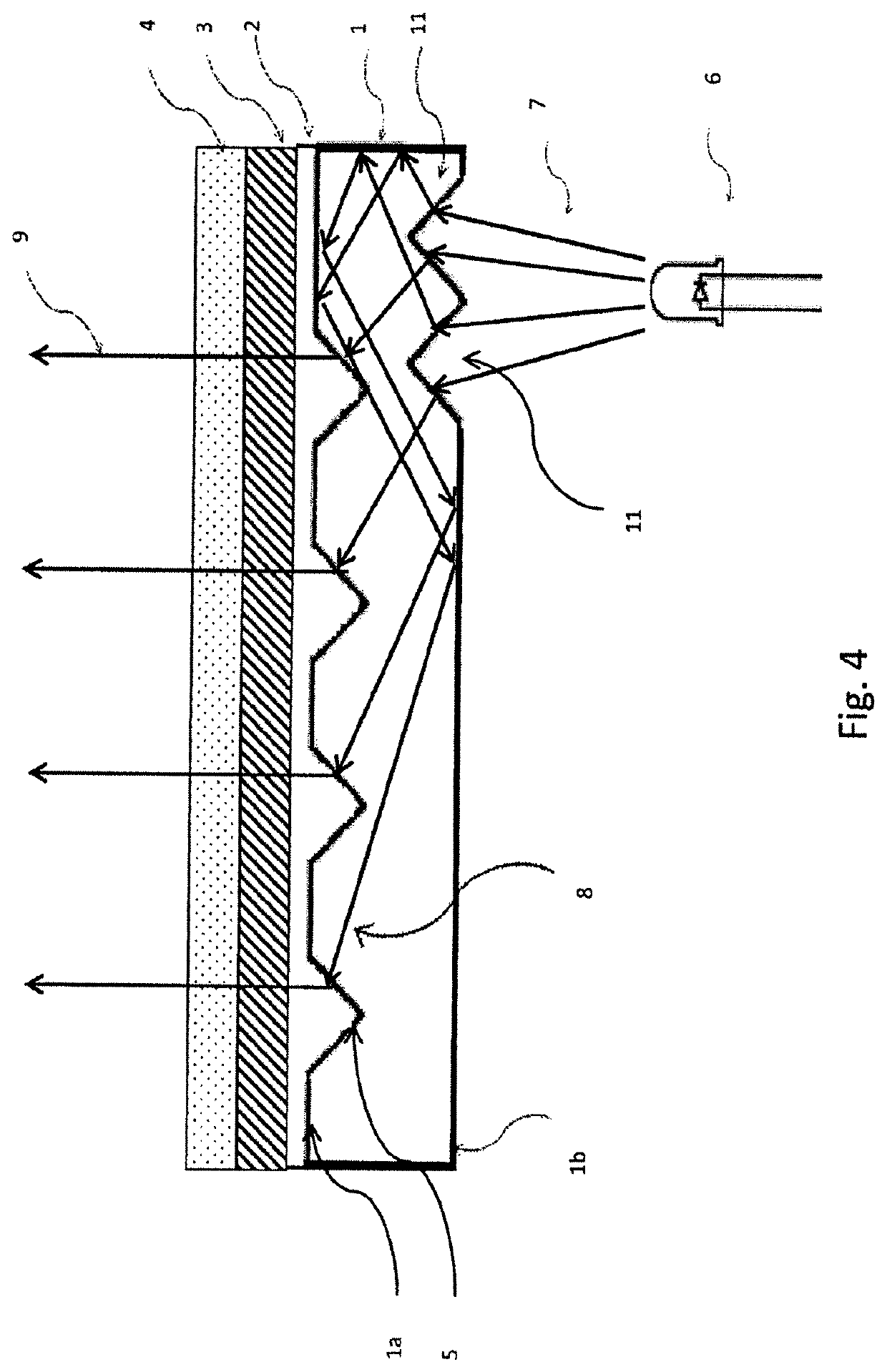
[0044]A preferred embodiment of the illuminant according to the present disclosure is shown in a schematic cross-sectional view of FIG. 1. The illuminant comprises a transparent substrate layer 1 with a first index of refraction, a connecting layer 2 with a second index of refraction that differs from the first index of refraction, and a metallic, translucent layer 3, wherein the connecting layer 2 is arranged between the substrate layer 1 and the metallic layer 3. The substrate layer 1 comprises a first side 1a facing the connecting layer 2, and a second, opposing side 1b. On the first side 1a, the substrate layer 1 comprises a plurality of decoupling structures 5 suitable for decoupling from the substrate layer 1 light 8 propagating within the substrate layer 1 in the direction towards the metallic layer 3.

[0045]In the illustrated preferred embodiment, the decoupling structures 5 are configured as cone-shaped cavities and / or recesses identical in dimension and shape. The cavities ...


PUM

PropertyMeasurementUnit
wavelengthsaaaaaaaaaa
thicknessaaaaaaaaaa

Abstract

An illuminant comprising a transparent substrate layer with a first index of refraction, a connecting layer with a second index of refraction that differs from the first index of refraction, and a metallic, translucent layer, wherein the connecting layer is arranged between the substrate layer and the metallic layer, and wherein on the side facing the connecting layer the substrate layer comprises a plurality of decoupling structures suitable for decoupling light that propagates within the substrate layer from the substrate layer in the direction towards the metallic layer.

Description

BACKGROUND1. Field of the Disclosure[0001]The present disclosure relates to an illuminant with metallic luster, and a method for producing such illuminant.2. Discussion of the Background Art[0002]In a wide variety of application fields, different illuminants are used to display information in the dark or mark structures by means of light. In many cases, however, it is not desired to have information displayed and / or marked permanently (e.g., under daylight conditions). Then, however, the means by which luminous information is displayed are usually still visible or discernible, which may impair the function of the respective product and / or have a disadvantageous effect on its aesthetics / appearance.[0003]To this end, DE 101 14 588 A1 and DE 201 05 140 U1, for instance, disclose a backlit plastic component for display and / or function setting elements, said component consisting of transparent plastic material and being vapor coated with a thin metallic layer, wherein one or more punctif...

Claims


Application Information

Patent Timeline
Patent Type & Authority Patents(United States)
IPC IPC(8): G09F13/08F21V8/00G09F13/18
CPCG09F13/08G02B6/006G09F13/18G09F2013/1863G09F13/04G09F2013/222G02B6/0036G02B6/005G09F13/049
Inventor KRUSE, KILIAN
Owner SINGULUS TECHNOLGIES AG
Why Eureka
Try Eureka