

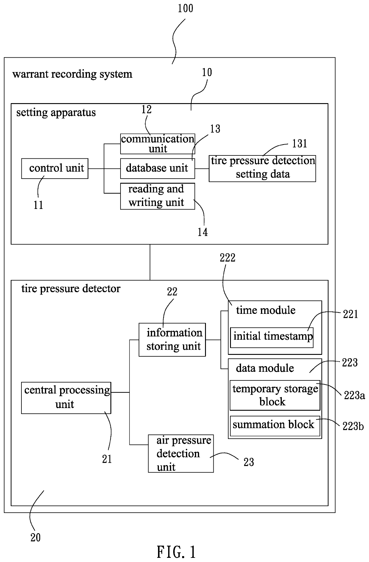
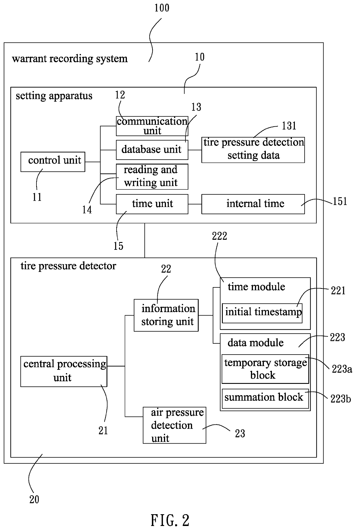
Warrant recording system and setting apparatus for pressure detector
a technology of recording system and setting apparatus, which is applied in the direction of instruments, tyre measurements, vehicle components, etc., can solve the problems of easy controversy of installation date identification afterward, easy writing error or blurred handwriting, and possible loss of warranty certificates, etc., and achieve the effect of efficient reading and writing
- Summary
- Abstract
- Description
- Claims
- Application Information
AI Technical Summary
Benefits of technology
Problems solved by technology
Method used
Image

Examples
Embodiment Construction
[0024]The aforementioned and further advantages and features of the present invention will be understood by reference to the description of the preferred embodiment in conjunction with the accompanying drawings where the components are illustrated based on a proportion for explanation but not subject to the actual component proportion.
[0025]The terms “a”, “an”, and “the” presented in a singular form, unless clearly indicated to be otherwise in the context, also include the embodiment with plurality forms. In the specification, the terms “be provided’, “include”, and “comprise” indicate that the cited technical features, components, and / or assemblies are included without exclusions of one or more other technical features, components, and / or assemblies.
[0026]Further, when a first component is described to be “disposed on”, “electrically connected with” or “coupled with” a second component, the embodiment includes that the first component is allowed to be directly disposed on, electric...
PUM
| Property | Measurement | Unit |
|---|---|---|
| time | aaaaa | aaaaa |
| temperature | aaaaa | aaaaa |
| pressure | aaaaa | aaaaa |
Abstract
Description
Claims
Application Information